Quick
Facts
|
Chemigation is an agricultural practice that uses irrigation water as a transport mechanism for the application of chemicals to soils and crops. Considerable interest in this practice has evolved during recent years due to increased energy costs and advancements in irrigation system design. Chemigation is not a new concept. Rather, the basic idea originated more than 25 years ago with the application of fertilizers through a sprinkler irrigation system (Bryan and Thomas, 1958). Recently, other chemicals such as herbicides, fungicides, insecticides and nematocides have been effectively applied with irrigation water.
Since the current emphasis is on total chemigation, i.e., both soil and foliar applied chemicals, sprinkler irrigation is the only irrigation method that lends itself to this practice. Other irrigation methods (surface and trickle/drip) can accommodate only soil applied chemicals.
Uniform application of the irrigation water is essential to ensure uniform chemical distribution over the field. Most sprinkler irrigation systems can be designed and operated to achieve good uniformity of water application. Solid set, periodic move (portable laterals and side rolls), and traveling big gun sprinkler systems generally have a coefficient of uniformity (CU) of 70 to 75 percent. The CU of continuous move systems (center pivots and linears) normally ranges from 85 to 90 percent (P ir, 1975).
Of the above-mentioned sprinkler irrigation systems, center pivots and linears are probably best adapted to chemigation because their coefficient of uniformity compares favorably with other application methods. However, as with aircraft and ground sprayers, the CU of these sprinkler irrigation systems decreases with increased wind speed. Also, steep slopes and hilly terrain may require pressure regulators on the sprinkler heads and higher operating pressures to get satisfactory uniformity of water application.
Advantages and Disadvantages
Many advantages accrue to chemigation. This practice has been demonstrated to:
There also are disadvantages associated with chemigation.
Of greatest concern is the potential pollution hazard associated with chemigation. Two specific hazards are: (1) the irrigation pumping plant may shut down from mechanical or electrical failure while the injection pump continues to operate, thus causing a mixture of water and chemical to backflow into the irrigation well or other water source; and (2) the chemical injection pump may stop while the irrigation pump continues to operate, thereby causing water to backflow through the chemical supply tank and overflow onto the ground. These hazards can be avoided through installation and maintenance of various safety devices.
Operations
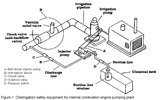
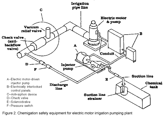
Interlock the irrigation pumping plant and the chemical injection pump to provide shutoff of the chemical pump if the irrigation pump stops. Interlocking the two pumps will prevent the possibility of the irrigation pipeline being filled with the chemical mixture from the supply tank. For internal combustion engine powered irrigation pumps, the chemical injection pump can be belt driven (Figure 1-A) from the drive shaft or from an accessory pulley on the engine. For an electrical motor-driven irrigation pump, a separate electric motor (Figure 2-A) is required to power the chemical injection pump. The electric controls for the two motors would be interlocked as shown in Figure 2-B to ensure that the injection pump motor stops when the irrigation pump motor stops.
Check and vacuum relief valves (anti-siphon device) are required in the irrigation pipeline. This check valve may sometimes be referred to as an anti-back-flow valve. These are shown in Figure 1-B and Figure 2-C. They keep water or a mixture of water and chemical from draining or siphoning back into the irrigation well. Both valves are located between the irrigation pump discharge and the point of chemical injection into t e irrigation pipeline. The check valve should provide a tight, positive seal and be installed to permit easy removal for maintenance and replacement of worn and non-functional components.
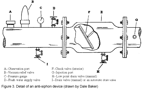
A suggested method of installation is to use bolt flanges as shown in Figure 3. Valves D and I (Figure 3) are recommended. Valve D provides a fresh water supply for clean-up; valve I is a manual drain to determine whether or not the check valve is functioning properly. An observation port (Figure 3-A) also could be installed as an additional method to determine the functional status of t e check valve. A third valve (Figure 3-H) is a manual low-point drain valve that would provide the capability to drain the water-chemical mixture from the irrigation pipeline. Valve I (Figure 3) could be replaced with an automatic drain valve that would automatically drain seepage (if any) through the check valve thereby ensuring that a water-chemical mixture could not backflow into the well when the irrigation pump stops. If the pipeline is drained (automatically or manually), this mixture should be contained, that is, not allowed to drain onto the ground.
A check valve in the chemical injection discharge line (Figure 1-C and Figure 2-D) also is required to stop waterflow into the chemical supply tank from the irrigation system. This valve sometimes referred to as an in-line check valve should be installed at the injection port (Figure 3-G) on the irrigation pipeline. Its function is to prevent a possible chemical spill at or near the irrigation well. In addition to this check valve, a small, normally closed solenoid valve could be installed in the chemical injection suction line (Figure 1-D and Figure 2-E.) This feature would provide a positive shut-off so that neither the chemical nor the water could flow in either direction if the chemical pump stops. An electrical interlock with the motor driving the injection pump would be required.
Automatic shut-down of the irrigation system, irrigation pump, and the injection pump if pressure is lost in the injection discharge line would be possible by installing a pressure switch in the injection discharge line (Figure 1-E and Figure 2-F). Primary reasons for pressure loss would be due to depletion of chemical in the supply tank, plugging of the filter/strainer, or injection pump failure. The pressure switch should be electrically interlocked with the irrigation system control panel.
Maintenance
of the installed safety devices is essential to ensure that
all equipment is functional. This will require frequent inspections
and possible replacement of worn and non-functional components.
As a result, chemigation will be a safe practice and not a
pollution hazard.


References
Publication #: 2.801
Cooperative Extension, Colorado State University. Published January 1985. Reviewed October 1992. Copyright 1992. For more information, contact your county Cooperative Extension office.
Walter C. Bausch, former Colorado State University Cooperative Extension irrigation specialist, agricultural and chemical engineering. Reviewed by Stan Pilcher, Cooperative Extension entomology agent, Golden Plains area.
Disclaimer and Reproduction Information: Information in NASD does not represent NIOSH policy. Information included in NASD appears by permission of the author and/or copyright holder. More