Chapter 1. Planning for the Unit
Chapter 2. Setting Up the Landing
Chapter 3. Machine and Equipment Inspection
Chapter 5. Setting Up the Yarder
Chapter 6. Rigging the Yarding Lines
Chapter 10. Worker Safety Rules
This handbook focuses on skyline yarding as the most common type of logging operation in Oregon, assuming steep terrain and use of a yarder tower and cable system. Basic information may also apply to other logging methods.
The material in the handbook is intended to reinforce safe practices in a hazardous work environment, based on Oregon OSHA Division 7 Forest Activities safety and health standards, and generations of practical experience in Oregon logging. The main intent is to provide loggers with a readable, easy-to-use resource.
This handbook does not contain all forest activity rules and is not a substitute for Oregon OSHA Division 7 – which should be consulted for a complete understanding of work safety rules.
Technical information is provided in some instances for quick reference, but loggers should also consult more complete technical manuals for specific topics, such as setting appropriate guyline zones or engineering specifications for alternative anchor systems. Always consult Division 7 work rules – which are continually reviewed and updated – and the manufacturer’s operating instructions for specific equipment.
Training is critical before working in the woods. Get hands-on training with a competent logger before engaging in any yarding and loading activity. This handbook provides useful information, but does not replace training in the field and supervised experience in the safe use of tools, equipment, and procedures.
Logging is a complex enterprise, and the challenge of organizing a comprehensive view of yarding and loading has been greatly helped by 40 years of attention to best practices in other published resources. Publications from Oregon, British Columbia, and New Zealand were consulted. Primary source materials included the following:
Illustrations in the handbook typically show model equipment and behavior. Negative examples are marked with the symbol ø. Please observe the difference.
Production of the Oregon OSHA Yarding and Loading Handbook included the following contributions.
Logging Safety Consultant: Jeff Wimer
Editor: Terry Hammond
Illustrator: Phil Fehrenbacher
Technical Review: Mike Lulay, Oregon Forest Activities Committee, Oregon OSHA
Planning a unit for logging requires up-front attention to work safety requirements. Implement the firm’s general safety and health plan, and then assess specific working conditions and hazards in the unit (see Chapter 10).
The unit plan will help ensure a safe and productive operation. The following items should be checked off before setting loggers to work.
[1] Hazard Assessment. Survey the setting for hazards, such as standing snags, rock outcroppings, stream buffers, or power lines. Pay attention to unique features of the unit. Topographical maps are useful. Determine ways to avoid or eliminate identified hazards in the work areas.
[2] Weather. Consider how the weather may affect the crew and roads. Snow, wind, and rain can create hazards. Pay particular attention to the roads and their ability to function in difficult weather.
IMPORTANT: Assess the ability of emergency personnel to reach the logging site in adverse weather conditions.
[3] Landing Locations. Identify the best landing locations and potential secondary locations. Usually, landings are already determined or choices are limited by the terrain. In some cases, the landing locations are left up to the logger. The best locations may not be clear until timber is on the ground. Assess the basic requirements for each potential landing, using the following criteria:
[4] Landing Size. Landowners or loggers will develop the working size of the landing according to production and safety requirements, involving the volume of timber, terrain, decking, equipment, and logging method (see Chapter 2). An initial assessment of the unit for landing locations should calculate the required minimum size for the following basic features.
[5] Haul Roads. Position machinery and arrange the sequence of logging to minimize conflicts with haul roads. Movement of log trucks on the landing should not interfere with the logging process. Consider how the road connects to the landing and how it relates to potential decking areas. Also, anticipate the interaction between the haul road and the ongoing logging and falling processes. It may be necessary to control access with flaggers at the landing or where lines cross the haul road.
Also consider the entire haul route. Look at the main county or state access roads and determine if there are any obstacles to moving heavy machinery, such as weight-limited bridges, unstable roads, inadequate road surfacing, overhead power lines, adverse grades, tight curves, and so on.
[6] Timber Cutting. Determine the method of falling. Terrain will dictate whether the unit will be mechanically felled or hand felled. The timber size, landing area, terrain, and machinery to be used will determine whether tree-length or log-length methods of timber cutting will be used. These decisions will affect the size of the landing and associated hazards.
Timber should be felled to lead to minimize risk to the rigging crew that follows. If snags or other hazard trees are left for the rigging crew, the unsafe timber needs to be clearly identified with hazard ribbon.
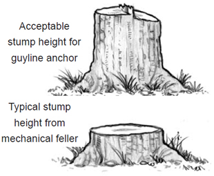
IMPORTANT: Communicate with fallers to save support trees that may be needed in the skyline corridors. Also, inform operators of mechanical fellers to save anchor stumps around all potential landings. Mechanical fellers typically cut timber close to the ground, which eliminates the possibility of using those stumps as anchors.
 [7] Anchor Requirements. For each potential landing, evaluate the available stump anchors and whether additional anchoring requirements will be needed. Other anchors include tieback or multiple stump anchors, deadman anchors, equipment anchors, and tipping-plate earth anchors (see Chapter 4). Timber size, logging distance, soil conditions, payload capacity, and machinery in use, all play a role in guyline anchor requirements.
[8] External Communications. Communication with emergency services and plans for emergency evacuation are essential elements of the safety and health program. Evaluate communication links and establish emergency plans for each proposed landing, including the following points:
Remote locations may have problems with communication dead spots, and may be difficult to access. If external communication is not possible at a landing, find a location nearby where communication works. Make sure everyone involved with the logging process is aware of points where external communication is possible.
[9] Internal Communications. During the operation, radios and signal devices are essential tools for communication. Determine in advance what machines and equipment will be necessary for the particular unit.
IMPORTANT: Register whistle systems with Oregon OSHA to ensure uninterrupted signals. By registering a radio frequency, interference, overlap, fadeout, and blackout can be eliminated or greatly reduced. (Register by contacting Oregon OSHA directly, or online at www. orosha.org under “Radio permits for forest activity.”)
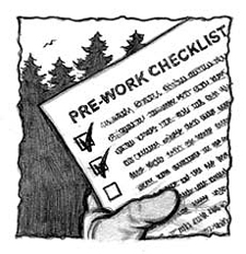
[10] Pre-work Safety Meeting. In the rush to start logging in a new unit, it is easy to forget to schedule a pre-work meeting with everyone on the logging crew. The importance of communication is too often underestimated. Don’t start work without a pre-work safety meeting. A pre-work meeting provides an opportunity to share information and begin thinking as a team. Loggers with expertise in different aspects of logging operations may be able to provide useful options and practical advice; and everyone together needs to become familiar with the particular hazards identified in the setting and how they will be eliminated or controlled. Discuss emergency communications and response at the meeting.
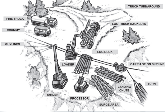
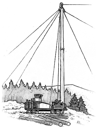
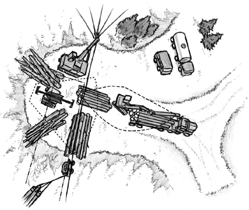
View of a typical landing
Each landing will present unique features in terrain, layout, and productivity. In a highly productive operation a lot of wood will go through the landing. An efficient layout that minimizes interference between machine operation and people on the ground increases both production and safety. Keeping the work flowing smoothly reduces the risk of an unexpected incident and possible injury. For best results, consider the following conditions before moving in to set up a landing.
Yarding system. Determine the yarding system to use, considering the available equipment, terrain, timber size, and yarding distances (see Chapter 6).
Size of timber and number of sorts. Tree-length logging requires much more room than log-length. Is there room to safely deck larger sorts of logs? Be sure there is a sufficient landing-chute area to safely land the logs.
Volume of timber. In highly productive sites, it may be necessary to include a surge area on the landing. This will allow the processor to deck unprocessed logs until incoming volume slows. Be sure there is adequate room to deck the volume of timber and expected log sorts.
 Slope of surrounding terrain. The slope of surrounding terrain dictates how logs will be landed, how many logs, and where they may be decked. On steep terrain, there may be a problem landing tree-length logs. Very steep terrain may make it impossible to increase the size of landing and decking areas, and requires machines and landing personnel to work in close proximity. In that case, the organization of the landing needs to be extremely efficient with space, and work processes need to be tightly organized to avoid interference between machines and people on the ground. Increased diligence is necessary. Communicate clearly in the planning stage, so everyone understands work procedures and hazards.
IMPORTANT: On small landings, plan in advance for situations where the loader operator may need to grab the logs to effectively land a turn, and hold them while the chaser unbells and hands them off to the processor. Prepare for runaway logs on steep terrain and keep the rigging crew well in the clear.
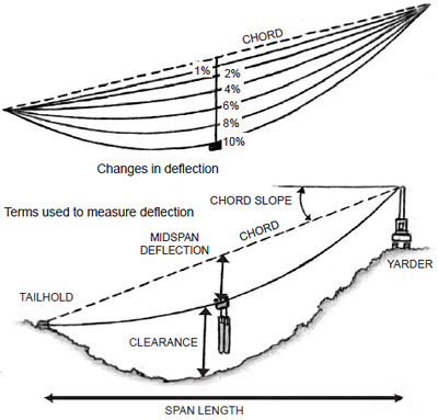
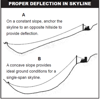
Deflection. Deflection is critical in logging with cable systems. Poor deflection will affect payload capacity and reduce production, and in some cases – as in going over a blind ridge to log behind that ridge – may make it impossible to tighten the lines enough to effectively get the logs off the ground. Many loggers can assess the terrain by eye. In uncertain situations, running a deflection line prior to rigging up allows a closer look at the terrain and a clear indication of how tight the lines may have to run. At this stage, the landings are already in place, and the logger will need to assess what deflection is available and choose an appropriate yarding system.
Payload analysis. There are several ways to analyze the payload for any given tower, landing, and terrain combination. Analyze the worst payload scenario for each landing to determine how much wood can be safely carried on the skyline. If suitable payload is not available with a tailhold down low on a unit, consider finding a tailhold up the back side, or use a tailtree to raise the line and give more deflection.
Guyline anchors. Locate and mark available guyline stumps suitable for the expected yarder locations. If appropriate stumps are not available, then other anchoring methods – such as deadman or equipment anchors – need to be established before rigging up the tower.
IMPORTANT: Communicate with the falling crew to be sure potential guyline stumps are not cut off too short at any potential landing sites. Some landing locations may not be identified beforehand, because the terrain can be seen much better once timber is on the ground. A different landing and set of anchors may prove more favorable. Also, plan ahead to preserve necessary tail and support trees.
Order of the skyline roads to yard. Normally, skyline roads work away from the side where the logging road enters the landing and the position of the log loader. Working away allows the log loader more room as the volume of logs accumulates. However, if the terrain creates a sidehill for the rigging crew, it is more important to log the felled timber from top to bottom for the safety of the crew. Then, the skyline roads might start farther away and move toward the loader. Plan road changes in advance. Also, consider obstacles that may obstruct moving the skyline.
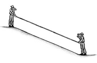 Running deflection lines involves use of clinometers and tape to show the profile of the terrain in a logging road. Two persons with clinometers stand at either end of a terrain break, with the tape running between them to establish the length and pitch of each break. Start at the back end of the landing and work down the logging corridor to just beyond the tailhold. The data can be analyzed by the “chain and board” method, or entered into a computer program like LoggerPC or SkylineXL (both programs are available from USFS or OSU). It may be possible to obtain this information from a topography map, government agency, or timber seller.
Deflection Lines and Haulbacks
Running deflection lines helps assess payload, lift, and the possible need for haulback use during yarding.
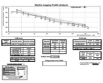
Payload Analysis
The payload analysis screen shown here from the computer program SkylineXL works on input for equipment and terrain to estimate an appropriate payload. Using a computer program is the easiest way to calculate payload. Adjust the estimate by additional variables related to the particular situation for environment, equipment, and human factors.
In most cases, loggers will come to a job with a set of machinery on hand. After evaluating the conditions at the landing as outlined above, the capacity of the available equipment needs to be reassessed to determine if it meets the task. Principal options and features are outlined below for yarders, log loaders, and processors.
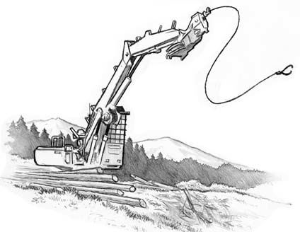
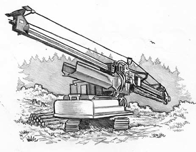
Yarders of various types have been around for more than a century. Early yarders were ground-based and relied on large rigging to move the turn of logs. Later, trees were rigged to lift the lines and allow the logs to clear most obstacles. Mobile steel towers were introduced in the past 60 years. Older mobile towers are still working, and new towers keep appearing. Always check the manufacturer’s manual for essential features and inspection points on each particular machine.
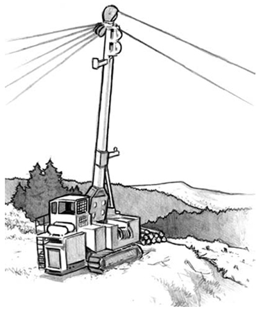
Straight tube telescoping tower. Uses a hydraulic ram or multiple-sheave cable system to raise the tower. Some telescoping towers allow use at the telescoped height or partially retracted, which can be an advantage if guyline anchors need to be placed closer to the landing or on steep slopes.
Travel: Self-propelled / Trailer mount / Track mount
Long reach; Height 90-110 feet
Advantages
Disadvantages
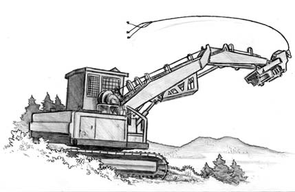
Fixed leaning tower. A one-piece tower can be front-mounted vertical, or leaning. The height of the tower varies with make and model.
Travel: Self-propelled / Trailer mount / Track mount
Medium reach; Height 40-80 feet
Advantages
Disadvantages
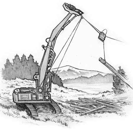
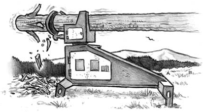
Swing yarder. Similar to the fixed leaning tower in nearly all respects. The swing yarder is also capable of swinging logs onto the road or landing. Capable of using a running skyline. Track mounts are more stable when moving.
Grapple yarder. Uses a swing yarder or yoader system. The grapple is controlled by signals from the rigging slinger, or by the yarder engineer using a video link on the carriage. Swing capability is necessary to allow a wider logging corridor. A grapple system is typically used in conjunction with a machine anchor and elevated support on the back end of the unit, making for quick road changes.
Travel: Track mount / Rubber-tire mount
Medium to short reach
Advantages
Disadvantages
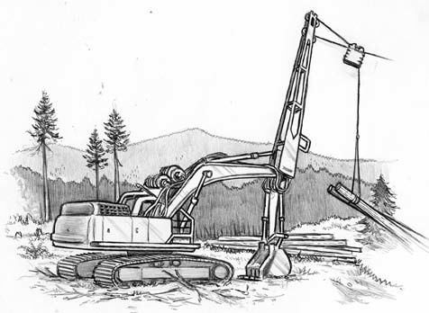
Yoader. This yarder is typically a log loader with two drums mounted at the base of the boom. Both lines run through sheaves mounted on the boom or heel rack. The lines can be set up in a standing, live, or running skyline configuration, or a high-lead configuration.
Travel: Track mount / Rubber-tire mount
Medium reach
Advantages
Disadvantages
Tong-tosser with grapple
Tong-tosser/Jammer system. These two systems use basically the same machine as the yoader, with either tongs or chokers on the end of the line to secure the logs. This version typically uses one drum on the machine with a spitter wheel at the end of the boom to pull the line from the drum and push it out to the brush. The yarder engineer usually gets the tongs or chokers swinging and then tosses them to the waiting choker setters.
Travel: Track mount
Short reach
Advantages
Disadvantages
Jammer system with chokers
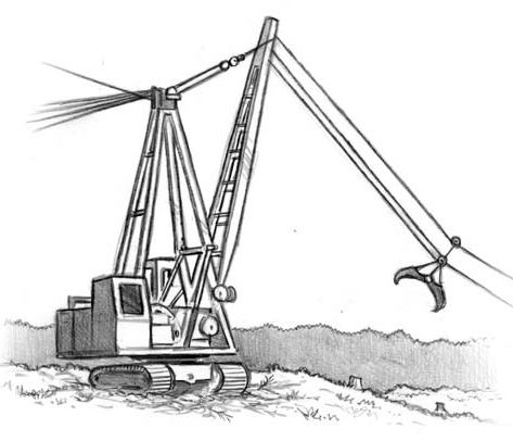
stiff-leg spar yarder
Travel: Track mount
Medium reach
Advantages
Disadvantages
The earliest way to move logs in Oregon followed ancient methods of heeling, rolling, and floating. Mechanized loading began with cable systems. Presently, hydraulic excavators with a log-loading boom load the majority of logs.
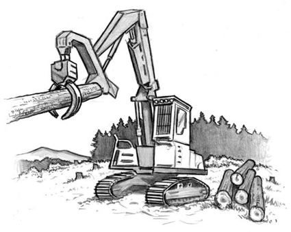
Track mount. Track-mounted loaders allow for easy movement in and around a landing area. They are slow to move over long distances, usually loaded on a lowboy for movement between jobs. On terrain where they can operate safely, some track-mounted loaders are capable of logging small areas around the landing or an entire unit.
Advantages
Disadvantages
Rubber-tire mount. Not as mobile as track-mounted loaders.
Advantages
Disadvantages
Ground-based processor. Pulls the stem through delimbing knives on top of the machine. Some have a saw for cutting stems to length.
Advantages
Disadvantages
Machine selection changes the way operations are organized, but a few critical factors apply to any landing. First, look at the landing again after the timber is on the ground to be sure what is needed. The original plan could change. Consider the following elements:
Landing size. The size of the landing is determined by conditions and machinery choices identified in the planning stage. The logging crew will need to decide how to best use the landing as planned. Confirm that the landing is large and level enough for safe movement, so machines or swinging logs will not strike standing timber, rigging, or other machines or objects. Also consider the surrounding ledges. Make sure logs can be landed and decked without risk of the logs or other materials sliding over the edge toward workers below. A landing that is too small can create safety hazards and delay production as machines, trucks, and logs compete for space.
Split landings. Split or jump-up landings may be necessary on steeper ground where one level area is not large enough to hold all of the machines, or would create greater risk to workers. Placing the yarder above gives the yarder engineer a better view of everything, but communication can be affected, because hand signals will be harder to use.
Landing chute. The yarder needs to be set back far enough from the front edge of the landing to allow logs to land safely. The landing chute should be at least two-thirds the length of the logs. Considerable hazards result when a log starts to run back downhill and the loader operator has to grapple the log to unbell the chokers. If logs need to be decked on the landing, make sure they will not slide or roll onto the crew below.
IMPORTANT: With tree-length logging, make sure longer trees can be safely landed, so they will not slide over the hill and strike the rigging crew. Logs for pole piling or an infrequent long break may be yarded, but the log must be secured before unhooking the choker.
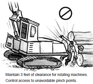
Operational zones. Each machine and vehicle at the landing site has a zone of normal operation. A minimum 3-foot clearance needs to be maintained between all pieces of equipment.
IMPORTANT: Pay attention where zones of operation intersect, and to potential impacts between machines, vehicles, and workers on the ground. Use barricades, danger ribbon, or other effective control measures to limit conflicts and worker access.
Downhill yarding. Downhill yarding requires a runout area to prevent material that may come down the hillside from striking the yarding equipment.
Surge area. When trees are felled and bucked, the log loader can take logs directly from the landing chute and place them in log decks for transportation. With the use of a processor, an intermediate surge area is often necessary, where logs are placed prior to processing.
IMPORTANT: Be sure the surge area is large enough that it will not be overloaded or create a hazard to the rigging crew below from rolling or shifting logs.
Log decks. A landing will commonly have multiple log decks, sorted for various destinations. With most log sorts, there are some that accumulate faster than others, and those should typically be closer to the landing operation. Consider the volume of wood that each sort will create when planning the decking area. Some landing areas may be so small that decking areas need to be created. Using tall stumps adjacent to the landing is one solution.
On smaller landings, establish procedures or control measures to avoid
impacts wherever zones of machine operation instersect.
Operational areas for the loader and log trucks. Set up the loading at the entrance to the landing, with the log decks on either side where the trucks back up to the log loader. On landings where a processor is working, the loading is separated, but not a great distance from the landing operation. The loader moves the logs between the yarder or processor to the log decks.
Debris area. As logging proceeds, debris accumulates in the landing area. If the debris needs to be placed over the edge of the landing, make sure it will not roll or shift and place the rigging crew in danger.
Haul road. Haul roads may access a landing from any direction. If a road runs through the middle of the unit, it may be necessary to have flaggers control traffic. Trucks usually back into the landing, so a turnaround should be not too far away.
Water and fuel trucks, and crummy parking. Consider where support vehicles will be located. During fire season, the Oregon Department of Forestry requires a fire truck to be available for immediate use. The crummy, which typically contains the medical and first-aid supplies, should also be available. Park nearby and leave unblocked to allow quick transportation. Plan where first-aid supplies will be kept whenever the crummy is taken for use in another part of the unit.
The following activities are essential in landing setup:
Communicate. Communication with the rigging crew and fallers is important while planning the landing to be sure the best falling leads and yarding directions are selected. Make sure all key members of the crew understand basic features of the landing and the operating plan. Control zones of intersection or potential impact. Make sure all landing workers understand restricted zones around each machine. Ground personnel must be aware of the blind spots for each machine operator.
IMPORTANT: Any time a worker in any of the landing processes steps out of the normal routine and into another operating zone (such as the chaser deciding to run into the landing chute to cut a limb), it is imperative that the worker communicate his intention to nearby machine operators before acting. Organize an efficient landing to minimize the need to step out of normal routine.
Remove hazards. Basic housekeeping on the landing is a primary safety feature. Keep the landing free of loose materials or debris. Other typical hazards, above and below the landing, include snags that can reach the landing, loose or overhanging logs, and loose rocks or boulders that could roll onto the landing or onto the rigging crew below. Guylines must not siwash any standing timber, because guyline pressure could cause a tree to fall over and strike a machine or worker on the landing.
Assess the stability of elevated areas around the landing. When a landing is lower than a nearby slope or a gradecut developed to clear the landing site, the elevated areas must be inspected and assessed for hazards. Loose rocks, stumps, logs, and other debris that could roll or slide downhill must be removed or secured. A hillside or gradecut above the landing should also be regularly assessed for slide hazards, especially after a heavy rainfall or a freeze/thaw cycle.
Maximize the line of vision of the yarder operator. Consider the yarder operator’s line of vision when choosing the yarder location on a landing. The yarder operator is in a central position to oversee all the visual, voice, radio, and signal communications from each member of the crew, and can warn workers or supervisors on the ground if an unexpected event occurs or one of the crew is out of place.
While setting up the landing, and before work begins, a competent person must evaluate work areas to determine if any tree or snag poses a hazard to workers. Identified danger trees must be felled, or the work arranged to minimize exposure. Danger trees that lean away from work areas may be left in place.
The following five-step process to evaluate danger trees summarizes a comprehensive plan in Field Guide for Danger Tree Identification and Response (2008) by the U.S. Forest Service Pacific Northwest Region and Bureau of Land Management. Consult the field guide for practical details, and use its color photographs to help identify specific defects and diseases.
 Step 1. Determine the type of work activity. Exposure is the first factor to evaluate risk. Consider three types of activity:
(a) traffic on roads,
(b) walking or nonmotorized activities that do not involve tree contact, and
(c) motorized activities that could contact the tree. Failure is more likely near active machinery.
Also consider exposure duration: intermittent, short duration, and long duration. Intermittent exposure includes drive-by traffic; short-duration includes staying near a defective tree for up to 15 minutes; long-duration includes situations such as parking at a trailhead, repairing a road, or working on a log landing. Traffic frequency modifies the term of exposure by accounting for many individuals together. Higher traffic means higher exposure.
Determining the type and duration of activity will help prioritize where to look for danger trees and how to judge them. On roadways, pay closer attention to blind curves, where a tree fallen across the road could surprise drivers. If a tree is a hazard no matter when it falls, the exposure to risk is much higher.
Consider Making a Record
An inspection record of danger trees can be useful if an incident occurs, and also useful as a reference for any later evaluation if the same location is used for logging activity. Suspect trees identified the first time but left alone will be easier to locate for a second look. A report form should include the following key details:
- location
- date
- species
- designated tree number
- height
- failure class (none, likely, imminent)
- expected work activity
- exposure
- how work activity could contribute to failure
- action taken
 Step 2. Identify tree defects and potential to fail. There are three levels of potential failure: low, likely, and imminent. Defective or rotten trees, snags, or their parts, have a low failure potential if they require considerable effort to make them fall, a likely failure potential if they require some effort to make them fall, and an imminent failure potential if they require little effort to make them fall.
Failure potential is a function of tree condition. Different species present different risks. Failure indicators include the following conditions that require an evaluation.
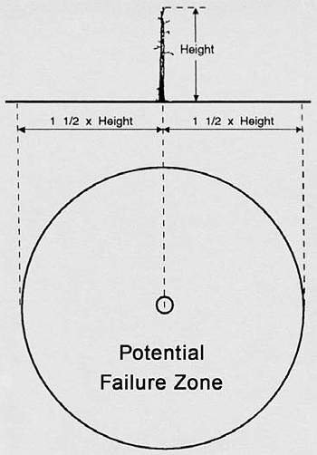
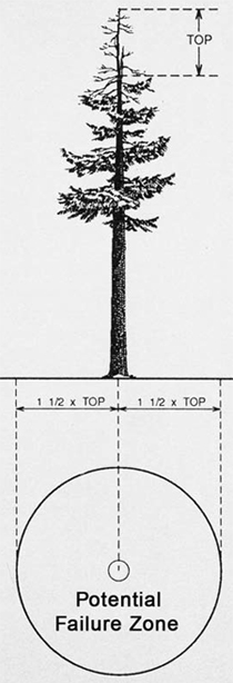
Step 3. Determine the failure zone. The failure zone is determined first by identifying the part of the tree likely to fail: the entire tree, tree top, branches, or bark. The failure zone is the area that could be reached by any part of a failed tree. The setting also matters. A failed tree on a slope can slide or roll; a failed tree could strike other trees and make them fail as well; or strike other trees or debris on the ground and fling material a considerable distance. Add distance to the failure zone as necessary to account for these additional factors.
On level ground with no lean, the failure zone is a circle around the base of the tree with a radius at least 1-1/2 times the tree height. With a leaning tree or a slope, the area behind the lean is not in the direction of fall, but is included in the failure zone to account for backlash (see diagrams).
Step 4. Decide if the tree is a hazard. Combine the points above – exposure level, failure potential, and failure zone – to decide if a tree should be classified as a danger tree. If work activity occurs entirely outside the failure zone, the tree is not a danger tree. Observe the following priority situations where action must be taken to control the hazard before work begins:
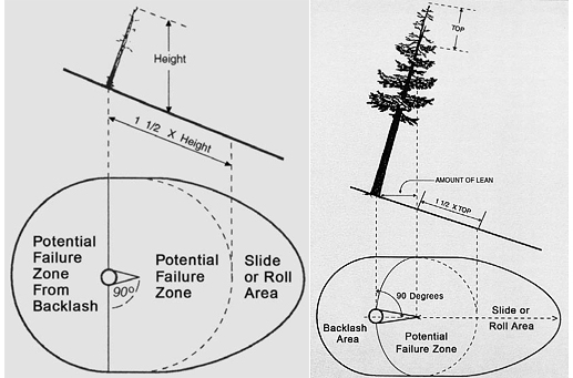
With a lean or slope, the amount of lean is measured as the horizontal distance from the base of the tree to the point where the part could dislodge. This distance is added to the failure zone in the direction of lean and out 90 degrees on either side of the tree.
Step 5. Specify the action to take. Following the evaluation of danger trees, the competent person making the evaluation needs to decide to remove danger trees or control the hazard by excluding access. If the failure potential is likely but not considered a danger due to the type or frequency of activity, the tree should be marked and workers informed so activity in the potential failure zone can be done quickly and without tree contact to minimize exposure.
Before setting up the yarder at the landing site, a competent person must inspect all machinery, tools, lines, blocks, shackles, and other rigging, and make repairs or replace defective equipment prior to use.
Machine operators must know the manufacturer’s recommendations for safe machine operation and maintenance, as well as safe work practices. Operators must inspect their machines each day before starting work, and make all necessary repairs and adjustments for safe operation before any strain or load is placed upon the machine. The engine must be off during inspection or repair, except when running the engine is necessary for adjustment or checking fluids. The machine must not be operated until all guards are reinstalled, safety devices reactivated, and tools removed.
Check machinery on a regular basis for cracks appearing in welds or in the steel plating. Repair defects before operation. A daily inspection to ensure safe operation must include the following items:
Metal towers and their appurtenances must be inspected by a competent person each time the tower is lowered, and at any time its safe condition is in doubt. Use the following list to check specific components on the yarder:
SAFETY TIP: Yarder control handles are commonly color-coded to match the color of the lead blocks and guyline drums they control to avoid confusion during use.
Check the spar closely for dents or deformation whenever it is raised or lowered, or if it has been struck. Lighter vertical tube spars are made from spiral rolled material and the slightest deformation will greatly reduce the strength. Newer towers with lattice boom construction are also greatly weakened by deformations or dents. If there is any doubt concerning damage to the spar, consult the manufacturer or a professional engineer before using the equipment.
Yarder spars are subjected to extreme forces, and over time, the metal will develop stress-related fatigue. Even if dents or deformations are not observed in the spar, it is extremely important to have it thoroughly inspected on an annual basis by the manufacturer or a professional engineer to prevent catastrophic failure.
The principle inspection method involves magnaflux and sample X-ray of the metal structure. This testing will detect stress-related fractures that may not be visible. The test will not determine if the metal alloys have lost their tensile strength. Unfortunately, the only current method to determine changes in the strength of the metal requires destructive testing.
Machine Shutdown Procedures
Hazards for machine operators are highest when entering or exiting the machine. Never start the machine while outside the cab. Start and operate only from the operator’s station or from a safe area recommended by the manufacturer. Never exit the machine without shutting down and securing all hazardous energy completely. Observe the following safety procedures:
- Lower blades, grapples, masts, or attachments to the ground or other stable surface.
- Shut down the engine and engage brakes to prevent movement.
Before any maintenance is conducted, make sure the pressure or stored energy in pneumatic storage devices that move machine elements is discharged. Use durable lockout tags over control devices, clearly saying “DO NOT OPERATE” or “DO NOT START” or another appropriate warning. Before lockout tags are removed, check the work area to be sure all tools have been removed, guards are in place, and workers in the clear.
Check the following components on the spar:
Make sure to regularly inspect carriages. Carriages typically see the highest amount of wear and tear. Ensure all hooks and shackles are the correct size for the lines. Also, check components according to the type of carriage and replace worn parts, as follows.
buttrigging
Buttrigging and Drift Carriages
skyline carriage
Motorized Carriage
Wire rope comes in many grades and dimensions, and every rope has its own characteristics with regard to strength and resistance to crushing and fatigue. A larger rope will outlast a smaller rope of the same materials and construction, used in the same conditions, because wear occurs over a larger surface. Similarly, a stronger rope will outlast a weaker rope, because it performs at a lower percentage of its breaking strength, with reduced stress.
Common grades of wire rope include extra improved plow steel (EIPS) and swaged powerflex, among others. The table below lists a few examples of wire-rope breaking strengths. The following terms are commonly used for wire rope:
Core. The foundation of a wire rope is made of materials that will provide support for the strands under normal bending and loading conditions. A fiber core (FC) can be natural or synthetic. If the core is steel, it can be a wire strand core (WSC) or an independent wire rope core (IWRC).
Strength. Referred to as breaking strength, usually measured as a force in pounds or tons. The breaking strength is not the same as the load limit, which is calculated as a fraction of the breaking strength to ensure safety.
Swaged line. Manufactured by running a nominal-sized line through a drawing die to flatten the outer crown and thus reduce the rope diameter. This compacted rope allows for increased drum capacity and increased line strength.
Die-form line. Made from strands that are first compacted by drawing them through a drawing die to reduce their diameter. The finished rope is then swaged or further compressed.
Abrasion resistance. Ability of outer wires to resist wear. Abrasion resistance is greater with larger wires.
| Typical Wire Rope Specifications | ||||||
|---|---|---|---|---|---|---|
| 6x26 Improved Plow Steel | 6x26 Swaged | Swaged Compacted-Strand | ||||
| Diameter (inches) |
Weight (lbs/ft) |
Breaking Strength (tons) | Weight (lbs/ft) | Breaking Strength (tons) | Weight (lbs/ft) | Breaking Strength (tons) |
| 1/2 | 0.46 | 11.5 | 0.6 | 15.2 | 0.63 | 18.6 |
| 9/16 | 0.59 | 14.5 | 0.75 | 19.0 | 0.78 | 23.7 |
| 5/8 | 0.72 | 17.9 | 0.93 | 23.6 | 1.01 | 28.5 |
| 11/16 | -- | -- | 1.10 | 28.8 | 1.18 | 35.3 |
| 3/4 | 1.04 | 25.6 | 1.37 | 34.6 | 1.41 | 42.2 |
| 13/16 | -- | -- | 1.56 | 39.6 | 1.63 | 49.3 |
| 7/8 | 1.42 | 34.6 | 1.83 | 46.5 | 1.91 | 56.0 |
| 15/16 | -- | -- | 1.95 | 53.3 | 2.20 | 66.1 |
| 1 | 1.85 | 44.9 | 2.42 | 60.6 | 2.53 | 73.7 |
| 1-1/8 | 2.34 | 56.5 | 2.93 | 75.1 | 2.97 | 92.9 |
| 1-1/4 | 2.89 | 69.3 | 3.52 | 92.8 | 3.83 | 112.1 |
| 1-3/8 | 3.5 | 83.5 | 4.28 | 108.2 | 4.62 | 128.6 |
| Source: Cable Yarding Systems Handbook. 2006. Worksafe BC. Table lists typical breaking strengths. See manufacturer's specifications for specific lines. | ||||||
Crushing resistance. Ability of the rope to resist being deformed. A rope with an independent wire core is more resistant to crushing than one with a fiber core.
Fatigue resistance. Ability of the rope to withstand repeated bending without failure (the ease of bending a rope in an arc is called its “bendability”). Fatigue resistance is greater with more wires.
High-tensile strength synthetic lines are coming into use in logging. Some lines are dimensionally as strong as standard wire rope, but are considerably lighter, as little as one-ninth the weight. Current use substitutes synthetic lines for brush straps, tree straps, tail and intermediate support guylines, guyline extensions, skyline extensions, and haywire. Manufacturers provide standards for determining usable life or criteria for retirement. Follow the manufacturer’s recommendations. Look for broken or abraded strands, discoloration, inconsistent diameter, glossy or glazed areas caused by compression and heat, and other inconsistencies. Rope life is affected by load history, bending, abrasion, and chemical exposure. Most petroleum products do not affect these ropes.
Wire rope must be inspected daily by a competent person and repaired or taken out of service when there is evidence of any of the following conditions:
Make a very close check of those points subject to the most wear, including the knob ends of lines, eye splices, and those sections of line that most often run through blocks or carriages. When in doubt, it is far safer to replace a suspect line, or cut out and resplice a defective area, than risk a failure during operation. Evaluation of the load-bearing yarder lines should be stringent. A competent person must also inspect all other lines used on site and remove any that are unsafe. Observe the following precautions.
Make sure the working load limit for any line is adequate for the intended task. Wire rope has an assigned breaking strength, determined by engineering test results, factored on the grade of the wire, number of strands, number of wires per strand, filler wire construction, lay pattern of the wires, and the diameter of the line. Follow the manufacturer’s specifications in determining load limits. The working load limit is a fraction of a line’s breaking strength – a factor of 3, or one-third the breaking strength, is commonly used as a safety factor for running and standing lines, when workers are not exposed to breaking lines or loads passing overhead.
Breaking strength safety factor
A safety factor of 3 is commonly used to determine the working load limit for a standing or running line. A standard 6x26 IWRC wire rope with a diameter of 1 inch has a breaking strength of 45 tons – divide by 3 – equals 15 tons working load limit.
WIRE ROPE OUT-OF-SERVICE EXAMPLE
A 6x25 IWRC wire rope = 6 strands in one lay with 25 wires per strand = 150 wires. The rope must be taken out of service when 12.5 percent, or one-eighth, of the wires are broken within the distance of one lay = 150 divided by 8 = 18.75, or 19 broken wires.A typical wire rope is labeled, for example, 6x25 FW PRF RL EIPS IWRC. The label indicates a 6-strand rope with 25 wires per strand (6x25), filler-wire construction (FW), strands pre-formed in a helical pattern (PRF), laid in a right-hand lay pattern (RL), using an extra-improved plow steel (EIPS) grade of wire, and strands laid around an independent wire rope core (IWRC).
 Consider high dynamic loads when calculating safe working limits. Wire ropes are often subjected to high dynamic loads, which greatly multiply the force on a line and may exceed the safe working limit. Even a split second over the limit can lead to premature failure of a line. Typical dynamic loads occur when a turn hits a stump, a turn comes down off of the back hillside to full suspension, or when excessive force is applied to pulling a turn out of its bed. A high dynamic load or a sudden shock load that exceeds the working limit may not result in immediate failure, but rope strands will stretch and weaken, and can fail at a later time.
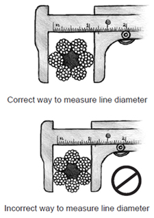
Measure line diameter to detect stretching. A stretched wire rope has a reduced diameter. Check for stretched lines by measuring the diameter, particularly on older lines and any line used in stressful situations.
Check date stamps and evaluate line life. Standing lines and guylines are often kept in service four to five years (and as long as 10 years) without exhibiting any signs of excessive wear other than rust. Inspect the core of older lines periodically for a fractured or dry core, which could indicate other deficiencies such as broken wires, excessive wear, or line deformation.
The life of a wire rope is also affected by hard use. Line life can be measured by the volume of wood hauled (see table above). Line life is reduced when a line exceeds its elastic limits, is heavily shocked, or rubbed against rocks or other lines. As a line wears, lower the safe working load limit and adjust the payload.
| Line Life by Wood Hauled | |||
|---|---|---|---|
| System | Use | Line Size (inches) |
Line Life (million board feet) |
| Standing Skyline |
Skyline | 1-3/4 | 20 - 25 |
| 1-1/2 | 15 - 25 | ||
| 1-3/8 | 8 - 15 | ||
| Mainline | 1 to 1-1/8 | 15 - 20 | |
| 1 | 10 - 15 | ||
| Haulback | 3/4 to 7/8 | 8 - 12 | |
| Live Skyline |
Skyline | 1-1/2 | 10 - 20 |
| 1-3/8 | 8 - 15 | ||
| 1 | 6 - 10 | ||
| Mainline | 1 | 10 - 15 | |
| 3/4 | 8 - 12 | ||
| 5/8 | 8 | ||
| Haulback | 3/4 to 7/8 | 8 - 12 | |
| 1/2 | 6 - 10 | ||
| Dropline | 7/16 | 5 - 8 | |
| High Lead |
Mainline | 1-3/8 | 8-15 |
| 1-1/8 | 6 - 12 | ||
| Source: Willamette Logging Specialist’s Reference by Keith L McGonagill. 1976. Portland, OR: Willamette National Forest. Calculations of line life refer to EIPS 6x21 wire rope for the skyline, and EIPS 6x26 for other lines. Figures will be different for other classes of wire rope. | |||
Working within the endurance and elastic limits of lines can help preserve line life. Use the following measures:
Check lubrication and abrasion. Wire rope is lubricated in the factory to reduce internal friction and corrosion, and prolong the life of the rope. Heat from friction causes the internal lubricant to deteriorate. Friction occurs when the rope stretches under load, particularly in places where it bends around sheaves or other objects. Commercial wire rope lubricants are available, and all lines should be kept properly lubricated, following the manufacturer’s instructions. An improperly lubricated line can pick up particles of dirt and sand that will increase abrasion. Inspect lines carefully for faults in areas where dust and sand collect. Store lines off the ground.
Regularly inspect shackles, hooks, splices, and other connecting equipment for damage and wear. Ensure the connectors are the correct type and size for the line and intended use.
Splices are used to form an eye at the end of a line, extend the length of a line, or repair a broken or damaged line. Splicing requires special skill and should only be performed under the supervision of a competent person with the proper tools. Reference books are available with detailed instructions for numerous splices. Always wear solid eye protection when splicing or helping with a splicing procedure.
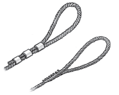
The logger's eye splice and three-pressed eye are the most common methods to form an eye for use as a skyline terminal. The spliced eye is approximately 80 percent efficient. A three-pressed eye can reach 90 percent line strength. The pressed eye is typically performed at the rigging shop. Spliced eyes can be placed in the field, but require time to install.
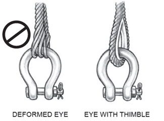
A line deforms where it loops around a shackle or pin, producing weakness that may result in line failure. A thimble in the loop protects the line. Thimbles work well on standing lines, but not on running lines.
Check that hooks have not sprung open. Make sure shackles are positioned correctly to bear the load. Haywire swivels in use must be inspected frequently, because they generally wear rapidly.
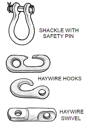
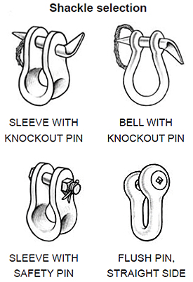
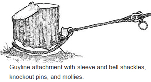
Proper bells or shackles must be used to connect the guylines to the stumps, and the guyline lead blocks to the ring at the top of the tower. Connections must have at least 1.5 times the strength of the guyline. The pins of the shackles must be secured against dislodgement, usually with a nut and cotter key, or a nut and molly. Some shackles may use a screw pin. The use of loops or mollies to attach guylines is prohibited.
The minimum sizes of shackles required for different uses, and other rules, are specified in the Forest Activities code (see tables, Div. 7, Sec. G, Shackles).
Observe the following points to use shackles safely:
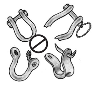
Replace shackles that are bent, broken, or show excess wear on the inner surfaces
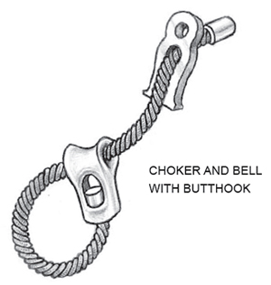
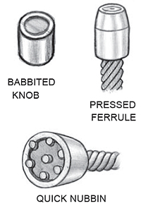 Knobs, Ferrules, Eyes
 Poured nubbins and a double-end hook are acceptable connectors in place of shackles in some instances. Oregon forest rules prohibit the use of quick nubbins as guyline and skyline end fittings unless attaching guylines to guyline drums. Follow the manufacturer’s recommendations when attaching sockets and similar end fastenings.
Poured nubbins achieve 99 percent of line strength; quick nubbins only achieve 65 percent at best. Pressed Ferrule are not certifiable for strength.
Inspect knobs, ferrules, and eyes at cable ends for loose or broken wires, and corroded, damaged, or improperly applied end connections. Poured nubbins must be date stamped.
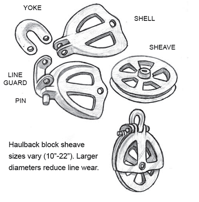
Check brush blocks thoroughly for cracks, wear, or deterioration. As with the lines, look closely at the points subject to the most wear – bearings, sheave, frame, yoke, pins – and replace defective parts immediately. Grease blocks each time before use.
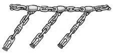
Always use chains or straps sized correctly for the intended purpose. Different factors apply. Oversized trailer lift straps, for example, must have a breaking strength equal to five times the load to be lifted. Towing chains must have a tensile strength equivalent to the gross weight of the towed vehicle. Always consult the manufacturer’s specifications or other reference materials to ensure the right chain or strap for the job.
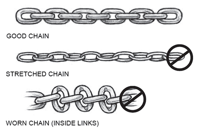
Periodically check chains for damaged, worn, or stretched links. If chains are used for hoisting or where individuals could be struck by a breaking chain, replace chains with more than 10 percent wear at the bearing surface. Periodically inspect straps, looking for broken wires or wear.
 NOTES: _________________________________
Anchors need to withstand significant forces to assure tower and rigging system stability. In general, remember the following critical points in anchor safety:
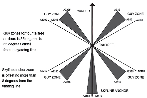
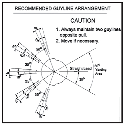
Ensure that guyline stumps or anchors are within the guy zones. Guy zones established by the yarder manufacturer, or established for lift tree stability, are designed to avoid catastrophic failure during the yarding process. Guy zones are set so the guylines share the load on the yarding lines. If anchors are not available in a guy zone, or at the extreme edge of a guy zone, reduce the payload or adopt other measures to ensure stability. It may be possible or necessary to rig an additional guyline.
A manufacturer’s cab decal shows a yarder setup with five guylines, which allows at least three guylines to oppose the load in a broader 60-degree yarding window.
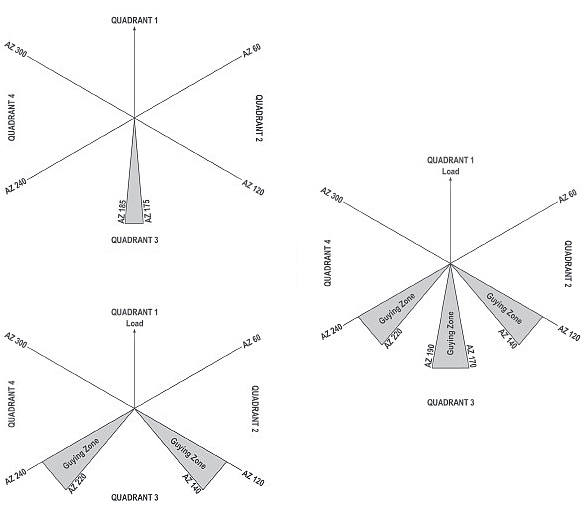
The above are examples of anchor placement within guy zones. Always follow manufacturer’s models or available technical manuals for anchor placement within appropriate guy zones. Oregon OSHA Division 7 Forest Activities rules show required guy zones for different numbers of anchors, one through eight, with variations suitable for tailholds and lift trees, as well as yarders.
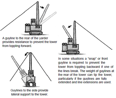
The angle of the guyline measured horizontally from the anchor point must be no greater than 50 degrees (or the manufacturer’s recommendation). Angles greater than 50 degrees can place a buckling force on the tower and cause a catastrophic failure. The flatter the angle, the more effective the anchor. An anchor above the height of the tower will be less stable. Guylines too far above the tower will create a lifting force that could actually lift the tower off the ground. Examine upward forces on the tower to assure stability. If a suitable anchor is not available, so a guyline exceeds a 50-degree angle, then additional precautions must be taken, such as adding guylines to oppose the load, or using narrower yarding roads or lighter loads.
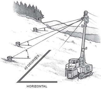
The angle of the guyline, measured from the horizontal,
must be no more than 50 degrees. Lower angles give greater stability.
Relative Stump Strength
Douglas fir is preferred for anchors or, if unavailable, white pine or hemlock. Use extra caution with spruce, cedar, or hardwoods – consider using tiebacks or other multiple support.
The holding power of a stump multiplies by the square of the diameter – so double the diameter gives four times the holding power. The equation is modified, however, by factors of soil and species, direction of pull, and zones and angles of the guylines. Before relying on an anchor, load to maximum and watch the stump for movement.
Choose anchors that are equal distances away from the tower or lift tree. Guylines that are shorter will tighten up quicker than longer guylines. A shorter guyline can take up the majority of the load and not share with the other guylines. This could overload the shorter guyline and cause it to fail. If anchors are not available equal distances from the tower or lift tree, make sure to adjust the tension on the guylines so all share the load.
IMPORTANT: Guylines that are straight back from the tower will load up quicker than guylines off to the side; a shorter guyline that is straight back will load up fastest.
Inspect all anchors daily. Yarding can reduce the strength of an anchor stump. High dynamic loads increase the risk of progressive failure. Check all guylines and anchors after several turns and on a daily basis. Look for signs of movement in stumps, mobile anchors, or buried deadman anchors. Any unstable guyline anchor must be immediately corrected.
Balance the load. The back guys on the yarder must share the load. Regularly recheck tension on the lines. If balance is neglected, the load may shift to one stump and cause that stump to fail (see Chapter 5).
Maintain adequate deflection. Inadequate deflection of the rigging lines can overload lines and increase the risk of rigging-system failure.
As the industry moves into logging smaller trees, adequate guyline stumps are harder to find. Faced with fewer options, loggers must be able to identify a good anchor and understand how the forces applied to a stump during the logging process could affect its holding power. If a single stump is inadequate, multiple stumps or alternative anchors must be used.
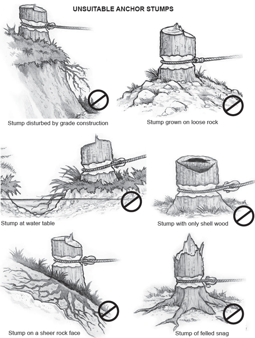
A competent person must carefully choose the skyline, guyline, and running line anchors for position and strength. Many factors affect the suitability of an anchor point. Avoid using unsuitable anchor stumps as shown on the following page. If such weaker stumps must be used, take extra precautions to assure stability.
Choose stumps rather than trees for guyline anchors. Tailholds and intermediate supports for the yarding lines may use trees as anchors and support, but the yarder guylines should use stumps to avoid the possibility of a tree falling on workers at the landing site during the operation. If a tree must be used, tie it back to prevent it from falling.
Carefully select the anchor stump according to the species, size, and terrain. Select anchor stumps for position and strength. Each species of tree has a different root system and grows differently according to the soil moisture, density, and slope. The holding power of a stump increases with soil depth and density. Never assume the stumps in one setting will be the same as stumps in the next setting.
Stumps are generally strongest with a side pull rather than an upward pull. On slopes, stumps have more root structure on the downhill side, and are therefore stronger on an uphill, rather than downhill, pull. Stumps on the back side of a ridge, with an upward pull, are stronger.
 Notching the Guyline Stump
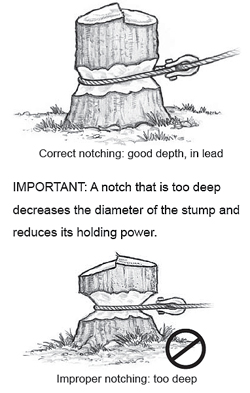
The common way to notch a guyline stump is with an axe or power saw. Clear the area around the stump to work safely; if using a saw, wear protective gear. Two basic points are critical when notching a guyline stump.
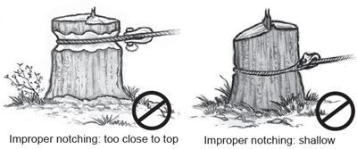
Depth. Stump anchors must be notched to a depth not greater than is necessary to safely secure the line to the stump. Cutting too deep reduces the diameter of the stump and effectively reduces its holding power.
NOTE: Deeper notching of swells, burls, and other irregularly shaped stumps is allowed so the line will be properly secured to solid wood.
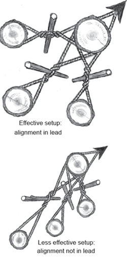
Position. Keep the notch in lead with the guyline and with enough wood above the notch to prevent slabbing. The notch needs to be as low as possible, but do not cut off the roots. By placing the notch low, less leverage is exerted that could pull the stump out of the ground.
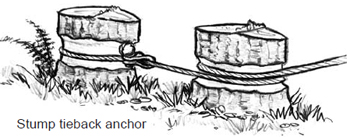
In the event that a single stump is not adequate, multiple stumps must be tied together or an alternative anchor type must be considered. If in doubt, use multiple anchors.
Avoid the zipper effect. Multiple anchors are only as strong as the weakest link. If one stump fails, the entire system can fail in a surge. If possible, isolate tieback stumps in multiples, so if one anchor fails, other leads will hold.
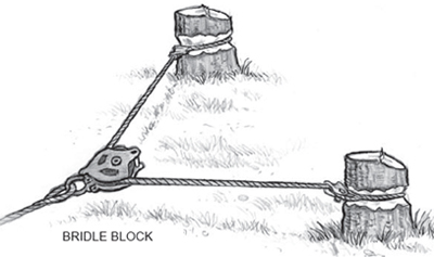
Common methods for combining the holding power of multiple stumps include (a) wrap and go back, (b) twister tie back, and (c) bridle block.
Wrap-and-go-back stumps wrap the line around a front stump and anchor to the back stump. The front stump may hold approximately two-thirds of the load force and the back stump one-third, if the line transfers the load. When three stumps are used, the load to the third stump is negligible.
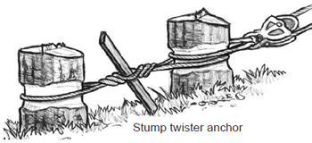
 Twister tiebacks only take a few minutes to set up. To do it well, consider the following guidelines:
NOTE: Synthetic rope makes effective twisters.
Bridle stump anchors have a line tied to each stump with a block that floats on the line, allowing an even distribution of force to each stump (see diagrams on next page). Never place a dutchman in a guyline in order to place the guyline within its guy zone. Instead, consider a bridle block or other means to bring the guyline into line with an even distribution of force.
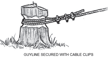
Guylines must be anchored to stumps with appropriate shackles or other connectors. When it is not possible to use a shackle and an eye to tie off the end of a line, then use cable clips or spikes to secure the line.
Both of these options require special care to avoid injury. When loosing the line, always consider where the tail will go if the line takes off running. Never stand on the outside of the line.
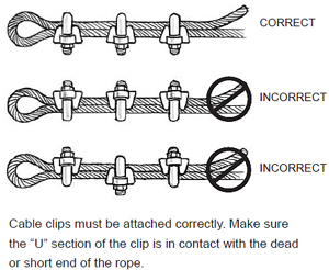 Cable clips are used to secure the end of lift-support guylines and jacklines. Select and notch a stump as shown earlier. Tighten the guyline or jackline using a rigging chain, come-a-long or power saw winch, or the haywire off the yarder. Take the end of the line and wrap the stump a minimum of three times, with the tail of the line pointing back at the support. Place the clips on the line as shown in the following images. Cable clips must be spaced at least six rope diameters apart. Nuts must be tightened evenly and rechecked after initial loading. When high-strength wire rope is used, one more cable clip must be added. (See Div. 7, Table 7-3 for exact number and spacing requirements.) When removing cable clips from stumps, a reverse safety wrap must be applied and secured before loosening the last wrap. If there is strong tension in the line, use a come-a-long, power saw winch, or haywire to assist in lowering the line.
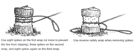
Spiked guylines are used in situations when additional guyline support is required and no drum is available on the yarder – typically for tailholds and supports for yarding lines. Spiked guylines require special precautions:
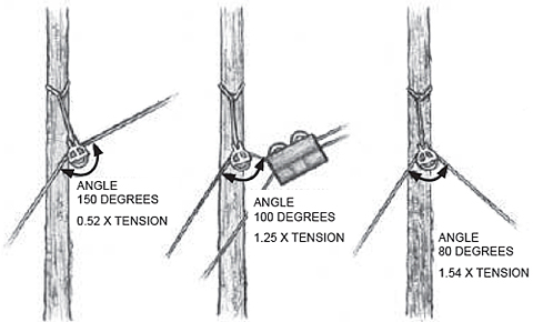
With a load of 10,000 pounds at a maximum angle of 120 degrees, each tailhold will receive 10,000 pounds of load. With a load of 10,000 pounds at a minimum angle of zero degrees, each tailhold will receive a load of 5,000 pounds.
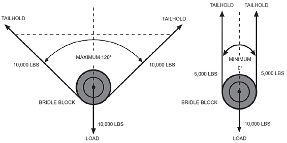
IMPORTANT: Never exceed an angle of 120 degrees between the two legs of the strap. Wider angles increase the force on each stump. Angles more than 120 degrees produce a greater force than the original load. The less angle the better.
When adequate stumps are not readily available, alternate anchoring methods must be considered. Alternate anchors are typically more expensive and require additional time, special equipment, and in some cases engineering to set up.
 Machine anchors are the most versatile of the alternate anchor systems. They are easy to move and rig, and the fixed size of a particular machine provides consistent performance in comparable load situations. Machine anchors may be used for guyline or tail anchors. They are not suitable where access is limited or in positions that could interfere with other activities or where soil disturbance is an issue. Of course, using heavy equipment as an anchor for its sheer weight underutilizes expensive machinery.
The two most common types of machinery used for anchors are bulldozers and excavators. The following factors need to be considered for any machine anchor:
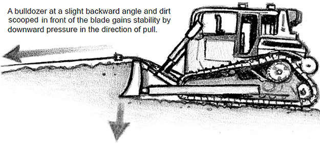
Size and weight of machine. The bigger and heavier the machine, the greater the holding power. Size is not the only factor. Follow the procedures for line attachment exactly to ensure the loaded line will exert downward pressure and maximize holding power. Experience is the best way to determine the stability of a particular machine. When experience is limited, apply lighter loads until assured of adequate stability.
Type of logging system. The type of logging system can greatly influence the forces being exerted on the machine. Uplift, side pull, or block purchase can all influence the holding power. When positioning the machine boom or blade, consider all forces being applied and compensate.
Condition of the soil and slope of the ground. Soil conditions and slope play an important role in the holding power of a machine anchor. Shallow or rocky soils will have less holding power than deep penetrable soils. A machine sitting on a relatively flat surface will have much more resistance to movement than a machine on uneven or downward sloping ground.
Holding aids. Look for embankments and stumps to help stabilize a machine anchor. With bulldozers, push a good volume of dirt in front of the blade; it is better if the bulldozer can be placed on the lower side of an embankment or with an upward slope.
Horizontal and vertical angle of the line. Stability of the machine is greatly affected by the angle of the attached line. An angle that is too steep can apply upward pressure that will reduce traction. Place the blade or boom so the pressure is applied straight on. Side pressure can make the machine tracks screw sideways or even overturn the machine. Tie back the machine to account for side pressures. Take extra precautions when multiple lines are attached.
Rely on a competent person
Any use of machines as anchors must be under the supervision of a competent person.
Anchor security. As with any anchor system, ensure that the slack is pulled or rendered out of the system, before a load is applied. Regularly inspect anchors for any indications of movement. A tieback to a stump can be used to add stability to the machine.
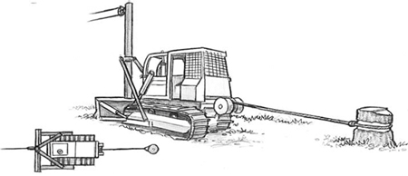
The following steps are a reliable method for rigging a bulldozer anchor:
As an alternative to passing the line over the blade to the back of the machine, a strap can be used for easier attachment. The strap must be at least the size and strength of the largest line attached to it. For greatest security, double the strap back from the rear of the machine and attach both eyes to the line at the front.
IMPORTANT: Never attach a line directly to the blade, which is not designed to withstand forward pressure.
 Excavators
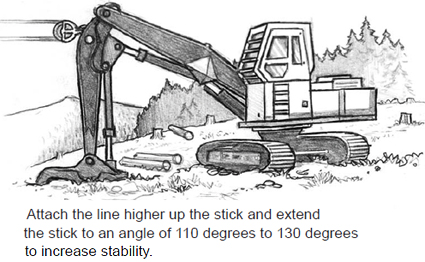
As with a bulldozer, attempt to find relatively flat ground for an excavator. Always face the direction of pull. Sideways forces are more of a problem with an excavator. The best position is up against a bank with the tracks parallel to the bank to oppose sideways movement. Sideways force can also be countered by orienting the tracks at 90 degrees to increase the effective width of the base.
Place the stick on the ground at an angle of 110 degrees to 130 degrees between boom and stick so the pull will push the stick deeper into the ground. Extending the stick more or less than this angle range will increase the lateral force and reduce holding power; less force will be directed down into the ground. Establish the attachment point on the boom as high as possible to maximize the downward pressure on the stick.
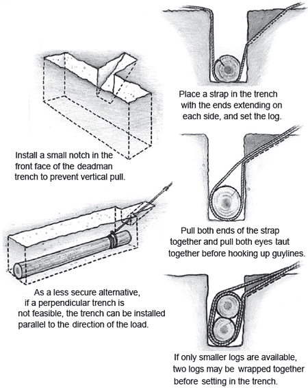 A deadman anchor is a buried log (or logs). Properly installed, a deadman anchor is more secure than an machine anchor and can be placed in uneven terrain or in areas where a machine anchor could be in the way of the operation. The deadman requires good soil depth, logs of adequate size and species (preferably fir), and the ability to get an excavator to the site to dig a trench. Second support logs may be required if there is a steep upward pull on the deadman or the single log is smaller than necessary. Observe the following steps:
IMPORTANT: Beware of trench hazards. Workers should not need to enter the trench, but if it should be necessary, special precautions must be taken for any person working in a trench more than 5 feet deep.
IMPORTANT: As the anchor point is brought closer to the yarder, the pull on the anchor is directed upward. A deadman closer to the yarder should be buried deeper.
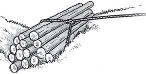
Log bundles can be used as an effective guyline anchor. A qualified individual must determine the maximum amount of pull that can be exerted on the line to be anchored. The weight of the bundle needs to be 2-3 times the exerted pull. The line needs to wrap around the entire bundle at its center, and the bundle positioned so both ends are secure and will not shift. The bundle must not be able to move.
Place in a ditch or up against a bank in the direction of pull. The anchor needs to be monitored until a competent person is satisfied with its stability.
Balance the Load on Multiple Anchors
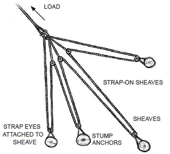
When using multiple minor anchors to support a line, take care to balance the load on the anchors. Use sheaves and straps to continually redistribute forces as the lines stretch and move. Without sheaves, one anchor can drop out, and the load will be shifted entirely to the remaining anchors.
Synthetic rope straps allow load sharing with variable lengths. Wire rope may require line clamps to align loading at proper lengths.
Rock anchors may be necessary when other anchors are not possible. They are rarely used in the Pacific Northwest. Installation requires special equipment and training, and they are more costly and time-consuming to set up. Always follow the manufacturer’s recommendations.
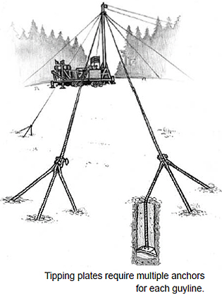 Tipping plate anchors are used in clay, sand, or gravel. Manufactured in a wide variety of shapes and sizes, they are effective when installed correctly. In some conditions, a pre-drilled hole is used, then backfilled. In softer conditions, special vibrating installation equipment is required to force the anchor through the soil to a predetermined depth. The anchor is set by applying a heavy load.
When using tipping plates, do not directly attach guylines, skylines, or mainlines to the anchors. Attach a strap or system of straps from multiple anchors to hold the line. The combined strength of straps or lines attached to multiple anchors must be equal in strength to the line held.
As with deadman anchors, do not bury the line; the line connectors must remain plainly visible for inspection. Spray-paint across the ends of the anchor line and the ground to supply an indicator for movement.
The yarder position was decided in the planning stage to minimize the number of times the yarder is moved on the landing. Set up the yarder to take full advantage of the first yarding window, and recheck the appropriate guy zones for the selection of anchor stumps.
Moving a yarder on uneven ground is always hazardous. Make sure the access road and the landing is well-chunked, packed, and level before moving in the yarder. Any time the yarder is moved, assign a spotter working on the ground to ensure the machine does not crush someone or something, walk off the road, or walk into a soft spot. The spotter is the eyes and ears for the yarder or truck operator moving the machinery. Establish clear communication between the spotter and operator with hand signals and/or radio communications. Be prepared to stop immediately with any sign of danger.
 Hauling yarders on logging roads is a common source of serious injuries. Many incidents are preventable. Observe the following precautions:
Plan the route. The yarder or truck operator must know the road conditions firsthand. Check for steep grades that will require assistance, load-limited bridges, tight curves, and weak subgrades. Reinforce or widen roads with surfacing, if necessary. Check overhead hazards, such as power lines and bridge obstructions.
Consider weather conditions. Will snow or ice be a factor? Will chains be required? Will rain cause the road to fail? Will steep grades be passable?
Inspect transportation equipment. Check equipment for operability before use, particularly the brakes. Make sure the equipment and tiedowns are adequate for the heavy load. Consider the length of the lowbed relative to tight corners.
Good communication is critical
Hasty decisionmaking and poor communication while setting up the yarder increase the risk of injury. Make sure all workers understand their own tasks as well as the tasks of others while working around the yarder. Workers should inform others when they begin a task, particularly if they move out of an expected position. Always use a spotter when loading, unloading, and moving the yarder. Make sure all workers are in the clear.
Use an experienced driver. Driving a lowboy requires a different skill set than driving a dump truck or log truck. Ensure the driver is qualified to handle conditions on the route.
Load and unload with caution. Loading and unloading heavy equipment is the most hazardous part of the operation. Make sure to load a machine on flat, even terrain with no overhead hazards such as limbs or power lines. Always use a spotter.
Consider weight distribution on the trailer. If there are adverse grades along the route, it may be necessary to load the machine forward on the trailer to add more weight to the drive axles of the truck and give better traction.
Lead with a pilot vehicle. A pilot vehicle leading the oversized load can let the driver know of unforeseen conditions well in advance, and also warn oncoming traffic to yield. In unfavorable conditions, a towing vehicle may be necessary to snub or assist in pulling the lowboy.
The siderod, hooktender, or other competent person supervising the yarder setup must know the manufacturer’s specifications for the yarder and know the appropriate rigging and procedures for the particular conditions at the site. Basic decisions will be guided by the manufacturer’s design specification plate located on the spar of the yarder, which displays critical information about the spar capacity, including maximum and minimum inclination for the spar; number, size, and breaking strength of the guylines and any other required lines; and maximum size and breaking strength of the skyline, mainline, and haulback lines.
Yarder selection for the job is critical. Using a smaller yarder to increase access to remote areas also forces loggers to push the outer limits of the machine. Long spans on midsized towers add extra stress to both tower and guylines. Whenever a midsized tower is used for an extremely long cable system, take extra care to rig the tower correctly, ensure the guylines are sharing the load, and analyze the payload for the tower-terrain combination.
Stability of the yarder is essential. Consider the following critical factors during the setup:
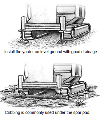
Place the yarder on solid, level ground. When working with heavy loads, changing the angle of force can make a huge difference to stability. Make sure the yarder is near to absolute level as possible and the ground is firm enough to avoid settling during operations. It may be necessary to crib a track with short log lengths set perpendicular to achieve a firm, level surface.
Assure good drainage. The solid surface for the yarder should be protected by assuring rainwater drains away rather than settling in pools under the yarder. Use slopes and channels directed away from the yarder. Laying down gravel can greatly improve drainage and prevent mudholes.
Install cribbing. A rock base for the yarder is ideal, but may not be possible. With softer ground, solid cribbing can be created with short log lengths positioned side by side. Log cribbing is commonly used to prevent the spar pad from settling. On uneven ground, it may be necessary to use cribs to bring the yarder level. Stack logs or short blocks of wood to achieve the height needed, and add layers crosswise. Make sure the materials are large enough that they will not crush or fail during the yarding process.
Guylines used to stabilize the yarder must be at least the size, strength, and number recommended by the machine manufacturer. Some yarders are designed to operate with fewer than three guylines. Proper placement ensures that all guylines oppose the pull of the yarding lines at all times.
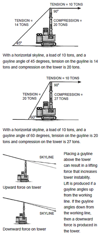
Guyline angles should be as flat as possible to avoid extreme tension. Greater angles produce greater tension. Tension in the guylines produces a downward force on the tower. Greater tension produces greater tower compression.
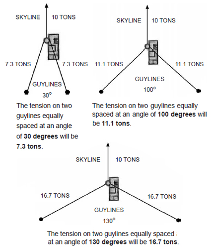
Horizontal angles in guyline placement also affect the tension in the guylines. As the angle between two guylines increases, the tension shared in those guylines increases. The figures below show results for different guyline configurations, with a 10‑ton load on a horizontal skyline, and guylines set at 45 degrees.
Guylines safety factor
Guylines help distribute the load from the yarding lines. A machine set up with one guyline back is considered to have a 1:1 safety factor (depending on how it is rigged). With two guylines, the safety factor is 2:1, and so on. It is important to consider the number of guylines that share the load when rigging a tower. An overloaded guyline system can result in tower failure. A minimum of three guylines is recommended for most yarding situations to assure a safer distribution of the load and provide increased support for lateral yarding forces.
Double-check that guyline stumps and other anchors are within the guy zones and guyline angles are less than 50 degrees. Stay within the guy zones recommended by the yarder manufacturer, so guylines share the load applied to the yarding lines. Recheck the guyline angles at this stage in the process to be sure they are flatter than 50 degrees. If guylines have to be rigged at an angle greater than 50 degrees, consult the yarder manufacturer.
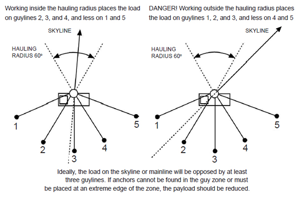
Know the limits of the yarding radius. The yarding radius, as shown in the yarder manufacturer’s operating manual, indicates the outer limits of the yarding forces that can be applied to the tower. The skyline and mainline need to be rigged within this target window. If the haulback is used outside the limits, or any side pull on the skyline pulls the skyline to the outer limit of the yarding window, the tower needs to be turned or the guylines moved to counter the forces being exerted on the tower. Make sure the force of the yarding line is always countered by at least three guylines.
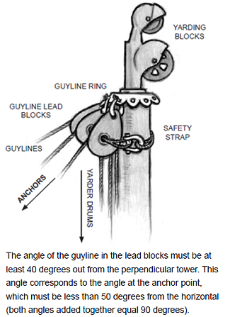 Use caution with long guylines. With normal rig-ups, guylines will extend back within a range of 2-3 times the height of the tower. If the guylines extend beyond this normal range, the weight of the guylines plus the tensioning force applied to them can exert enough weight and force to tip a tower over backwards. With vertical tube-type towers, an unwritten rule said guylines should never extend out beyond five times the height of the tower. No similar rule-of-thumb exists for new leaning-type towers, which gain additional support from the yarder base. Be sure to know the specific capacity of the tower used to avoid tipping over due to longer guylines.
Long guylines also increase the amount of sag, or belly, which can cause a problem once the skyline is tightened up. The tower may move out of plumb before the guylines come taut. In that case, consider pre-tensioning the guylines: pull the tower out of plumb to account for the belly so the correct level results once the guylines are tightened. Use caution to not pull the tower so far out of plumb that it tips and falls.
If a guyline is too short to reach the anchor, a guyline extension must be added in the same size and condition as the guyline, attached by a shackle or guyline sleeve.
Make a clear path. Guylines must not rub against any tree or obstacle. If necessary, cut a corridor to a guyline anchor.
Know when to use snap guylines. When there is potential for the yarding line system to fail (tailhold failure, skyline breakage), it may be prudent to place a snap guyline out in front of the yarder to prevent the rear guylines from pulling over the tower. A snap guyline may also be necessary when numerous guylines are used or extrme tension is applied to the yarding system. The haulback can be used as the snap guyline. The biggest disadvantage to snap guys is they are often in the way during yarding and loading.
Ensure the guyline ring at the top of the tower is turned so the guyline blocks are in line with the intended guyline anchor. Proper alignment will ensure no sudden movement of the ring causes a shock to the tower or guyline block. Before raising the tower, ensure that the safety strap is in good condition and the strap ends are properly secured.
Once the guyline stumps have been selected and notched, and the placement of anchors is double-checked, stringing and attaching the guylines to the stumps is the final step in raising the spar. The structure and weight of the guylines usually require the use of a haywire to pull the guyline to the stump.
Two methods are typically used: (a) a haywire is attached to a guyline and carried out to the anchor and strung through a block to return to the yarder to pull out the guyline, or (b) the haywire is attached to a guyline and pulled with a vehicle from the yarder to the anchor.
Beware of the hazardous forces involved in this phase of work. Observe the following precautions.
Work safely with haywire. The haywire is typically attached to the eye of a line or hooked several feet up the guyline with a rigging chain to make it easier to connect the guyline to the stump. Once movement begins, stay in the clear – the chain may slip.
Use spotter with a haywire vehicle
Care must be taken when attaching guylines to a vehicle to pull them off the yarder. Pulling too fast or too hard can upset the tower. The yarder engineer needs to be in control at all times. Use a spotter to communicate between the yarder engineer and the vehicle operator.
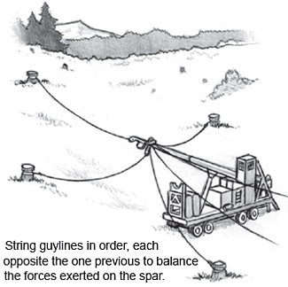 Pay careful attention to the stability of the spar. During this stringing process, the spar is only held up by the raising system on the yarder. Stay aware of the forces exerted on the spar and avoid unnecessary loads on it. Use a bubble level to monitor tower movement. Stay out of the bight of the spar in case it should suddenly drop. Refer to the manufacturer’s instructions if there is any question about how high the spar can be raised without the support of guylines. Some telescoping spars have auxiliary safety guylines to anchor before the main guylines are strung and the top section raised.
The guylines must be strung out in an order that ensures the stability of the spar. With vertical towers, ensure guylines are strung with opposing lines in succession to prevent all of the weight pulling one side of the tower. With a leaning-type tower, pull out the side guylines first, work to the center, and do the back guys last. Work so that tightening any one guyline will not tip the tower.
Avoid siwashes. A siwash is a bend in the line under tension, commonly caused by obstructions from saplings, stumps, or roots. A siwash in any line is extremely dangerous. When stringing the lines, make as straight a line as possible from the yarder to the stump, and go over the top of all debris. When tensioning the lines, be alert for hang-ups and correct immediately. Never assume a haywire is free of siwashes.
The bight of the line in a siwash is a direct hazard, but a siwash can also throw material considerable distances. When the line gets passed underneath a log as the line is strung out, it can throw the whole log when the line is tightened.
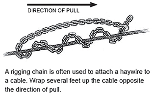
Once the yarder is securely positioned and leveled, the rigging and fittings checked, all the necessary greasing completed, and the guylines strung, the spar can be raised. Every yarder is different in the way it is raised. Some require the use of guylines, others use hydraulics only, and others use various combinations of lines and hydraulics. Follow the manufacturer’s instructions. All line movement must be accompanied by proper whistle or hand signals. Keep people in the clear.
Stay clear of moving lines!
Get clear of haywires under tension and stay alert for thrown material. Siwashes are common. Signal “stop” and wait for a full stop before approaching to clear a hang-up.
Rig lines to support the spar in case the raising system fails. Front guylines can assist in raising the tower, so if a jack or raising line fails, the front guylines will keep the tower from falling down onto the machine.
Angles are critical in load-bearing lines. Keep a vertical spar perpendicular to the base of the yarder, even if the base cannot be made absolutely level; that means, install cribbing or blocks according to the position of the yarder, not the position of the ground. This will avoid damage or failure in the equipment. Any off-angle in the spar will increase stress on the top of the spar during operations, and make extra guyline support and caution necessary. A tower out of lead may also cause the lines to spool incorrectly on the drums. Some manufacturers allow for rigging a tower out of level. Follow the manufacturer’s recommendations, and know your machine.
Inspect and maintain jacks regularly to be sure all hydraulic lines and cylinders are in good condition. During use, make sure the jack is secure. Workers have been injured by blocks kicked out sideways from under a jack or by being sprayed with high-pressure hydraulic oil from broken lines.
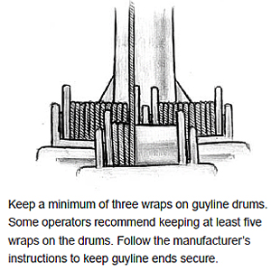 Spooling Lines
 Caution is necessary when unspooling and spooling lines on the yarder drums to protect workers, the lines, and the yarder. Observe the following precautions:
Use tower safety straps
Use safety straps and other equipment to prevent the fall of the guyline or guyline attachment in the event of failure. Straps must prevent guylines from falling more than 5 feet. Use appropriate strap connections, following the manufacturer’s instructions.
Secure line ends. Make sure the ends of lines attached to drums are secured by end attachments, and keep a minimum of three wraps on the drum at all times (or more as recommended by the yarder manufacturer). When lines are pulled off the yarder and then respooled onto the drum, lines can acquire a twist if the end comes free of the drum or the anchor point. The twist can be controlled by using a swivel at the point of attachment. Use caution when disconnecting a line pulled from the yarder.
Avoid crushing and chafing. Always make sure to spool lines neatly onto the drum. A crossed line can be crushed or malformed and cause premature failure of the line. Use a tool or the haulback to apply pressure (snub the line) and guide the line in layers onto the drum. Depending on the yarder drum configuration, it is better to spool the bottom layer of line with a 1/16-inch gap between lays. The small gap allows the bottom layer to flatten slightly without crushing or chafing, and allows the above layers to spool correctly.
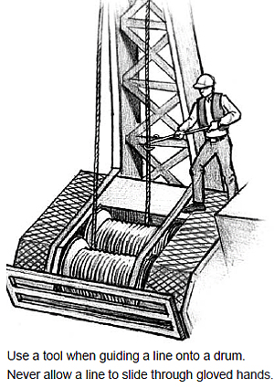 Work carefully near moving lines and drums. Workers helping to guide lines onto yarder drums must stay alert to the high hazard of working near both rotating machinery and moving cables. Observe the following precautions:
Tension lines on alternate sides to keep the tower in balance. Working one side at a time could tip the tower. Do not lock in the guyline dogs until final tensioning. Leaving the dogs out during the initial tightening will allow rapid relief on a guyline if a problem occurs. Once the tower is fully rigged, pre-tension the guylines close to their final tension and raise the skyline to its safe working limit.
Before moving any line, sound the yarder whistle to make sure everyone is in the clear. Observe all anchors as the skyline is raised. Once up, check for proper deflection.
Typically, tightening the last guyline can slightly loosen the previously tightened guylines. When the skyline is in position, strike each guyline in pairs to feel if they are approximately the same tension. This method of comparing pairs of guylines gives a close estimate of how guylines are sharing the load. More exact methods should be used when there is any doubt or when the tower will be stressed to its working capacity. If the guylines are not balanced, lower the skyline and adjust the guylines as needed.
Once all lines are in place, recheck the guylines for correct tension to ensure they still share the load. Test the setup by passing several light turns over the system first, and recheck all the anchors again. Look for any signs that stumps, mobile anchors, or buried deadman anchors have moved. Check all connectors to ensure they have not shifted or are coming unconnected.
After several initial turns (and daily) recheck all guylines and anchors.
Guyline layers and drum torque
A full guyline drum reacts differently than an empty drum, because the torque changes as spooled line increases the working diameter of the drum. Layers of line on a drum are like gears in a transmission: the first layer like low gear, exerting high torque at a low speed, and the top layer like high gear, with low torque at high speed. Operators should use extra caution when guylines are extended far out, leaving an empty drum. The drum’s extra torque can over-tension a line.
[1] Position of Workers
[2] Guylines Anchors
[3] Level and secure yarder base
[4] Back Quarter Guys
[5] Initial Raising System
[6] Lift Spar Off the Initial Raising System
The checklist for raising the spar reinforces important procedures. Every spar is a little different. Make sure to follow the manufacturer’s instructions.
Towering down and moving
Procedures for towering down depend on the design of the tower. Usually, just reverse the steps to raise the spar.IMPORTANT: Assure spar stability by keeping all guylines attached to the stumps until the spar is resting in the saddle or has been lowered to the first stage on the telescoping spar.
- Except for the front quarters, the dogs must be set once the guylines have been slacked off. If the slack must be picked up on a guyline, the dogs must be kept in position.
- Reposition leveling blocks and jacks (if removed earlier). The blocking makes it easier to judge the side angle of the spar as it lowers.
- Provide adequate slack to prevent the mainline or haulback from pulling tight and fouling. Rather than continually unspooling, alternately slack the front guys as the spar is lowered onto the raising cylinder (some machines make this procedure unnecessary). Keep the back quarter guys snubbed up until there is no danger of the spar being pulled forward.
- Once the tower is down, unhook the guylines from the stumps and remove shackles and hooks to prevent hang-ups as the lines are spooled in. Use caution, in case guyline stub connectors hang up.
Before moving the yarder, the engineer must recheck to make sure the machine is in safe operating condition. Give special attention to brakes and steering.
Tow or snub the yarder when necessary to prevent a runaway. Drive in the center of any roads, away from soft ground, particularly when traveling across fills, culverts, and bridges. There are times, however, when it may be best to put wheels in a ditch line to prevent a runaway or from sliding off the road. The operator should know features of the road beforehand, including the location of culverts and other objects in the ditch line.
There are several procedures for road changes that involve stringing haywire through blocks at the new road line, then tightlining the yarding lines to the new location. Sometimes this is a clearly quicker choice, but these kinds of “jumps” in the line can be hazardous due to potential hang-ups and siwashes. Even moving lines no farther than toward the corner block in the existing layout produces a very large bight area. Workers must stay well clear during line shifts that jump lines directly to the new location.
When jumping heavy lines on slopes or uneven ground, use a chain to keep the line from running away when the haywire is released. Attach the chain to the line and to a sapling or secure object.
Examples on the following pages illustrate ways to rig-up and change roads in different setups.
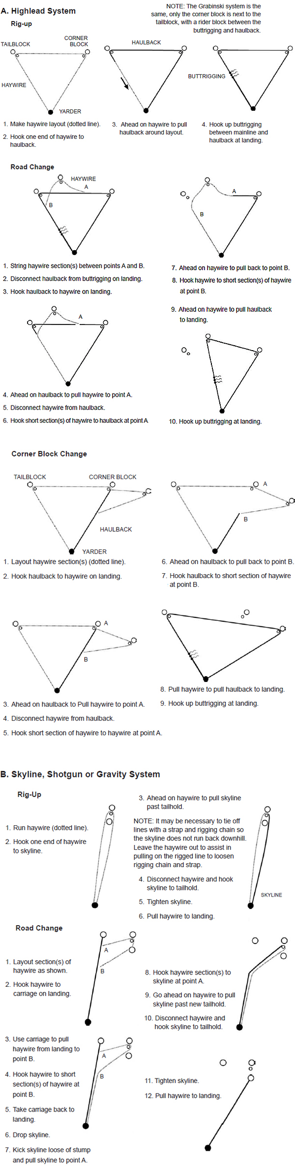
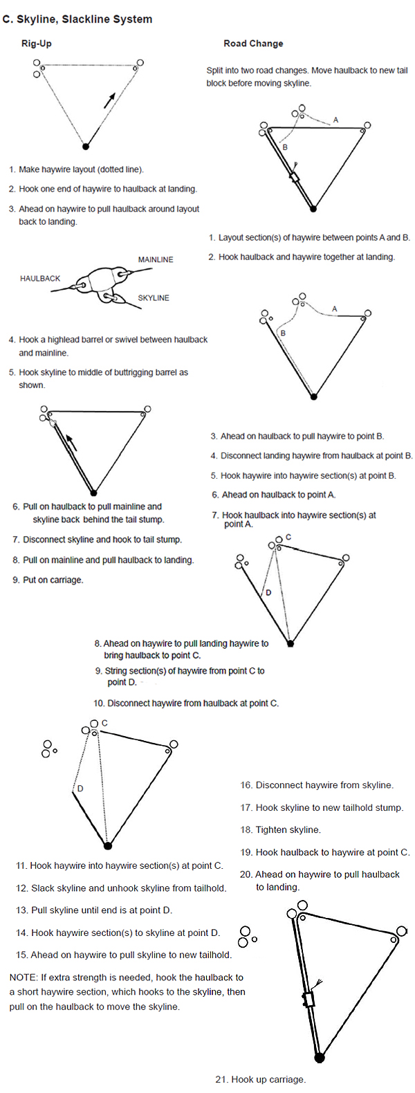
Locate yarding roads to minimize hazards from runaway logs dislodged by yarding or loading activities. On sloped ground, the first yarding road should be strung to the highest point of the setting so the crew can remain in the clear on the upper side and in the logged-off area after the first road is yarded. This procedure is also convenient for recovering runaway logs on the lower slope.
More than one rigging system might be used for different parts of the unit, according to available equipment, terrain, and the distance to be logged. In any yarding system, calculate the payload capacity to achieve optimal efficiency without overloading the system. The most common yarding systems used in Oregon are described on the following pages.
IMPORTANT: Maximize deflection for best results.
Common cable logging systems
Carriage and rigging systems
Factors in Calculating Payload Capacity
Calculating the payload capacity for a given yarding system involves many factors. Optimal capacity can be estimated with a fairly exact number from yarder specifications, and lines and angles in the setup, but other factors may only suggest degrees of caution rather than definite answers. Consider the following variables when determining payload capacity, and use a generous safety factor for caution wherever numbers are missing (see payload analysis in Chapter 2).
__Anchor strength __Guylines in guy zones __Guyline tensions __Lifting capacity of carriage
__Number and position of guylines opposing the load __Deflection __Span length
__Full vs. partial suspension __Timber size __Terrain __Age of tower __Age of lines
A standing skyline system uses a skyline, mainline, and sometimes a haulback, with a motorized carriage or skycar with a slack-pulling dropline. Lowering or raising the skyline during the cycle is not necessary.
A standing skyline in a gravity-fed (shotgun) configuration with a motorized carriage is the most common yarding system used in the region. Carriage outhaul works by gravity. The slackline configuration requires a haulback, using a three-drum yarder, with the additional line attached to the rear of the carriage. The system works with an adjustable dropline, motorized or mechanical, which allows a wider yarding road and selective logging.
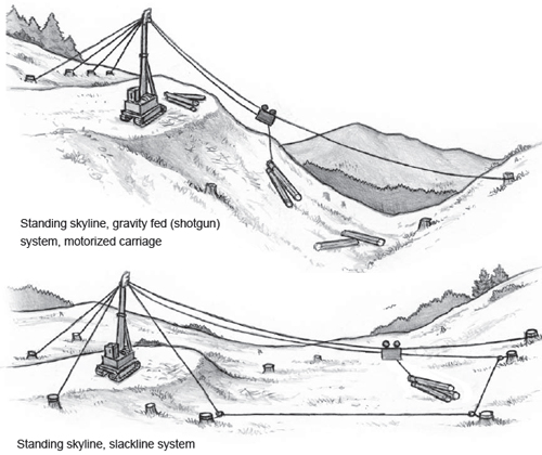
Advantages
Disadvantages
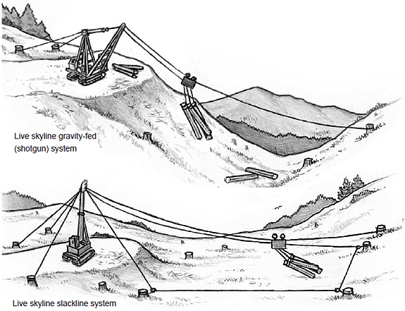
A live skyline is the second most common system used in the region. A live skyline uses a skyline, mainline, and a carriage with fixed chokers, requiring the skyline to be lowered and raised for each cycle. The choker length limits the width of the yarding road. In a shotgun configuration, the outhaul works by gravity. A slackline configuration, used when the slope or clearance is limited, requires a haulback.
Advantages
Disadvantages
Highlead is the simplest (and once the most common) cable system, without a skyline or carriage. Two drums on the yarder operate a mainline on the lead end and a haulback on the tail end. Chokers are connected to buttrigging on the mainline. Turn suspension is the most limited of any yarding system. Lift is achieved by braking the haulback to clear obstacles. This method of achieving lift requires considerable power and can overheat the haulback brake. Ideally, there should be a clear line of sight between the turn and the top of the tower; an intermediate ridge can foul the turn. Additional lift is possible by adding a rider block on the bight of the haulback, connecting it to the buttrigging on the mainline with a strap. This modification of the highlead system uses the haulback as a running skyline.
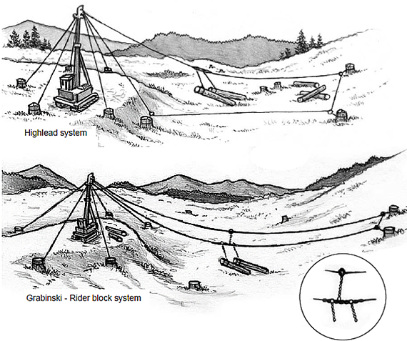
Advantages
Disadvantages
A running skyline system with a manual slack-pulling carriage uses a moving mainline and haulback, with an additional mainline to work the dropline. This system allows partial or full suspension of the turn. The running skyline can also be used with a mechanical grapple, ideal for larger timber and shorter distances. The grapple is supported by a rider block on the haulback line. The second mainline opens the grapple. Running skyline systems work best with a larger swing yarder with interlocked drums. A swing yarder also extends the width of the yarding road, and is easier to move. Grapple systems generally use a mobile tailhold.
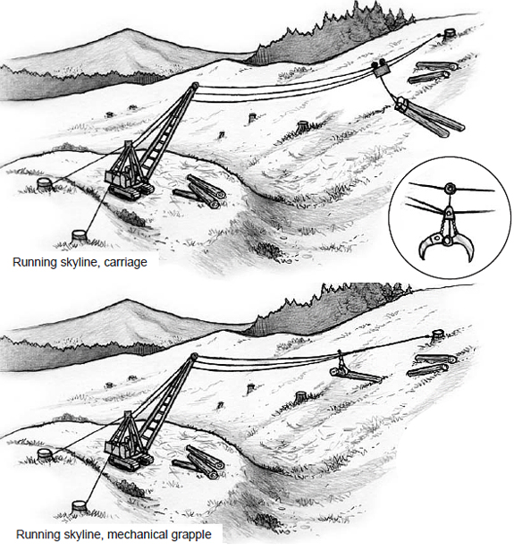
Advantages
Disadvantages
Side blocking uses a standing or a live skyline, a mainline, and a haulback to pull the skidding line (mainline) and buttrigging out to the turn. The system is used to expand the logging road without changing roads and is good for picking up small corners or areas between roads. The mainline passes through a fall block where the buttrigging is attached, and connects to the carriage riding higher on the skyline. Connection to the skyline carriage allows full or partial suspension. A simple nonmotorized carriage is typically used. Two simple side blocking systems, northbend and southbend, are easy to set up from a highlead system. The southbend differs only by adding a sheave below the carriage where the mainline passes to provide additional lift.
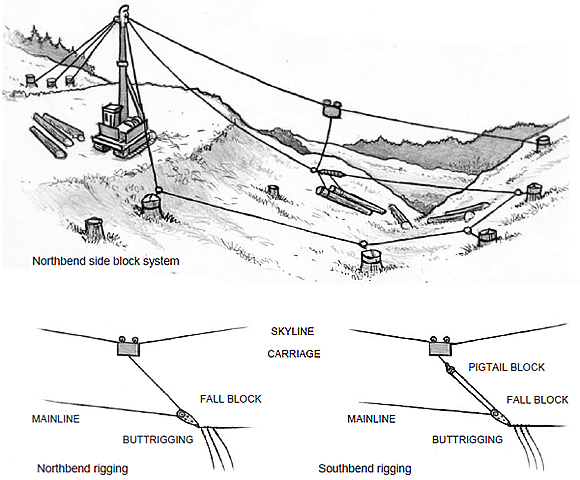
Advantages
Disadvantages
These two variations provide lateral pull on the skyline: useful when there are limited tailhold options or to pick up a small corner of the unit when a road change would be impractical. In the dutchman system, the haulback runs through a block or multiple blocks on the side that needs to be logged and attaches to the skyline through a block on the skyline. Tension on the haulback pulls the skyline to the side and allows the rigging to travel down a new logging road. In the eaglebinski system, the haulback attaches to the drop line of the carriage, either directly or by placing a buttrigging carriage between the two lines.
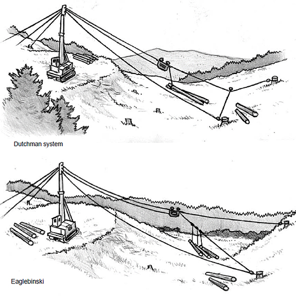
Advantages
Disadvantages
Working in the Bight
In side block and fall block systems, and the dutchman and eaglebinski, the skyline being pulled to the side is not as much of a concern as the huge bight area created by the side blocking. The angles and extra line in the system can make it confusing for the ground crew to figure out where to get in the clear. Also, the sideways arc in the rigging during outhaul can make spotting the rigging more difficult for the rigging slinger. The carriage may need to be stopped some distance before the hook-on point and slowly advanced to judge the final position.
The arc in the path of the carriage depends on the type of lateral yarding system. Usually, there is no side pull until the rigging reaches the logging area, which makes it difficult to judge the path away from the normal road line. During inhaul, the tension on the haulback may be used differently according to the load, and the arc of the rigging will move on a different path. With the dutchman system, the haulback is typically always kept taut to pull the skyline to the side, which actually makes it easier to judge the bight area.
With any of the lateral yarding systems, use extra caution to limit exposure to the bight. Get in the clear farther from the turn to account for the extra line lengths that produce a much larger hazard area. When working near the haulback tailblocks, move well clear in case a block fails.
Deflection increases the payload capacity of a yarding system, as illustrated in the following table.
Deflection
percentGross Load
Capacity
(pounds)4 3,000 6 5,500 8 8,500 10 11,000 12 13,500 14 16,000 16 19,000 18 22,000 20 24,500 Example: Unclamped carriage, 2,000 ft. span, 40% downslope, 1-inch EIPS skyline – 103,400 lbs. breaking strength, 34,500 lbs. safe working load; weight 1.85 lbs./ft. Terms of Measurement to Calculate Deflection
Chord = A straight line from the top of the tower to the tailhold.
Span length = The horizontal distance between the tower and the tailhold.
Deflection = The vertical distance between the chord and the carriage at midspan.Deflection is typically expressed as a percentage of the span length.
Deflection (%) = Deflection x 100 Span length
In any rigging system, use lines appropriate for the load and protect the lines from excessive wear during use. Observe the following points:
Do not use oversized lines without taking additional safety measures. If the skyline, mainline, skidding line, or haulback line in use are a larger dimension or greater breaking strength than allowed by the yarder manufacturer (recorded on the identification plate on the side of the yarder), some type of load-limiting device must be used to control the load on the tower, such as a certified fuse link that will break before the tower is overloaded, a tamper-proof tension-limiting device, or other similar equipment. If the system is suddenly stressed, with a properly rigged tower, the main lines or an installed breaker device in the lines should release the tension or break first before the tower or guylines fail. If no such system is in place, operating procedures must be established that will limit line loads (pull) on the tower to below the listed maximum.
Maintain proper payload and deflection. Every road has a payload maximum that depends on deflection and location on the yarding road as well as the basic capacity of the yarder and rigging. Maintain proper deflection while logging according to what was calculated in the setup as necessary for the expected payload. As deflection decreases, tension in the line increases dramatically (see table above).
Excessive line wear and stretching occurs when using less than 8 percent deflection. Minimum recommended deflection is 10 percent. If this cannot be attained, use a tailtree or intermediate supports, or lighten the payload.
Account for rigging load zones. Distribution of tension to the mainline, skyline, and haulback (if used) depends on the position of the load on the skyline. Tension on the skyline is greatest at midspan. Beware of rigging failure midspan. In the back quarter, tension on the skyline is reduced. In the front quarter, close to the landing, tension on the skyline is least as the mainline and haulback take more of the load.
Account for suspension. Consider the extra load when using full suspension on turns. In partial suspension, the ground partly supports the load and increases rigging system capacity. Full suspension requires the rigging to support the entire load and decreases payload capacity. When full suspension is necessary, due to terrain or to reduce forest damage, reduce the payload.
Develop procedures to avoid overloading the system. Consider operational procedures that will limit the potential for overloading the tower. Always remove or deactivate dogs on the yarding drums before logging begins. Make sure dogs on the guyline drums are securely seated. One load-limiting procedure involves setting the air pressure on the skyline brake so the line strips off the drum before the line is overloaded.
Regularly check line spooling on the individual yarding drums. Incorrectly spooled lines will allow lines to chafe or become crushed, reducing their life expectancy and risking failure.
Vary the skyline position on the tower. Keeping the skyline in the same spot in the sheave at the top of the tower can result in excessive wear. Reposition the skyline occasionally so the line does not prematurely fail at that spot.
Suitable anchors are chosen by the same principles as the guyline anchors discussed in the previous chapter. If the capacity of a stump is questionable, tie it back. Notch the tailhold and haulback stumps in the same way as the guyline anchors. Double-wrapping a stump to avoid notching is prohibited.
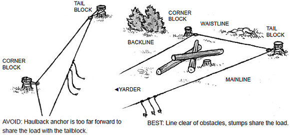
All lines must run clear of obstructions to avoid burning the line and any potential siwash. Remove any major obstacles in the bight of the line and clear an area around the anchor stumps. In haulback systems, a second stump anchor for a corner block works best to keep the lines from burning and the chokers free. A corner block on about the same line as the tailblock will help share the load and increase the payload capacity.
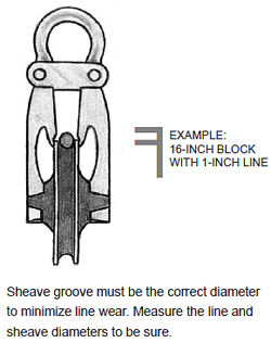 Blocks are commonly used on yarding lines to turn the direction of the line and distribute stress on anchors and attachments. Considerations must be made to not overload corner or tailblock attachments or anchors. Tailblocks are less strained when the load is shared by a corner block. Use blocks appropriate for the job with sheaves large enough for the wire rope used.
The line attachment for a block is stronger when hung in both eyes of a strap. Always hang straps in lead with the load. Never choke a stump with a strap by threading one eye through the other (except for haywires or other light loads); the line could cut through itself and fail.
Refer to Division 7 for required shackle sizes to hang blocks (Table 7-4), join lines (Table 7-5), or attach skyline extensions (Table 7-6). In addition, observe the following precautions:
Line and shackle sizes
Consider the type of line and not just line size to select the appropriate shackle. Consult Oregon Division 7 standards, manufacturer’s recommendations, or other reference sources for appropriate shackle use.
| Strap Sizes for Rigging at Ground Level (inches) | ||
|---|---|---|
| Skyline or Running Line | Block Hung in Both Eyes | Block Hung in Single Eye |
| 5/16 | 1/4 | 1/2 |
| 3/8 | 1/4 | 9/16 |
| 7/16 | 5/16 | 5/8 |
| 1/2 | 3/8 | 3/4 |
| 9/16 | 7/16 | 7/8 |
| 5/8 | 5/8 | 1 |
| 3/4 | 3/4 | 1-1/8 |
| 7/8 | 7/8 | 1-1/4 |
| 1 | 1 | 1-3/8 |
| 1-1/8 | 1 | not permitted |
| 1-1/4 | 1 | not permitted |
| 1-3/8 | 1 | not permitted |
| 1-1/2 | 1-1/8 | not permitted |
| 1-5/8 | 1-1/4 | not permitted |
| Source: Division 7, Table 7-7. | ||
Maintain Proper Line Angles on Shackles
When wrapping a strap with two eyes around an anchor for a corner or tailblock, the attached shackle to secure the line must be far enough from the anchor to make an angle of the two lines from the bell of the shackle less then 90 degrees. Wider angles increase loading on the stump.
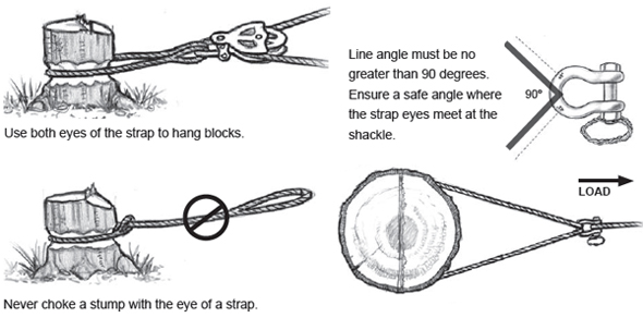
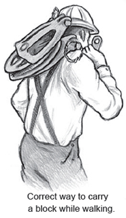 Blocks are heavy and awkward, and carrying blocks in the brush can be hazardous. To avoid back injury, lift the block from a stable stance with knees bent. Pick up the block by the gooseneck, not the sheave, and swing it onto your back, high between the shoulder blades. This position allows the block to be held in place with one hand, leaving the other hand free to keep balance while walking. Keep mollies away from your neck or face to avoid cuts.
If you trip while carrying the block, throw it clear. Do not, however, intentionally throw blocks down bluffs. Damage may occur to the block that is hard to see.
Haywire is usually strung by hand to pull the skyline out or pull the haulback around. A common procedure involves the use of several haywires pulled from the yarder: one to the tailblock and one to the corner block, with a connection in between. This procedure spares the effort of pulling one line all the way around. Make sure the connection is secure and will not come loose when the haywire is slack.
IMPORTANT: Pull out the haywire as straight as possible in lead to minimize bights and siwashes.
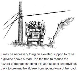 When the haulback is run around, the hooktender should watch the tail and corner blocks to ensure the lines are running clear in the blocks, the straps and blocks are properly aligned, and the straps are correctly positioned in the stump notches. In addition, observe the following precautions:
Using a lift tree to elevate a tailhold or intermediate support may be useful in situations where the terrain limits skyline deflection and reduces the payload. Lift trees also increase rigging clearance, allow turns over a blind ridge, and increase haul distances.
The most common elevated support is a tailtree used to elevate the skyline and provide better deflection. Intermediate tailtrees are used to raise the skyline in a central part of the span.
Several critical factors apply to any lift tree:
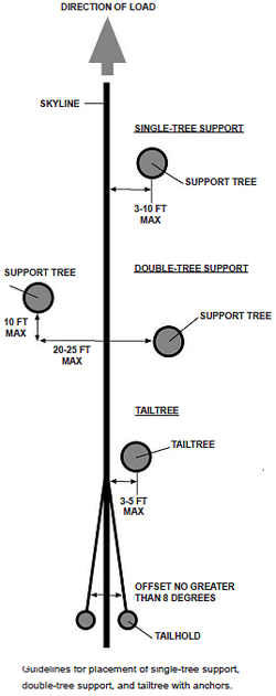 Use only sound, sturdy, well-rooted trees, straight up to the point of attachment. Species of high strength are preferable, such as fir, spruce, or hemlock. It may be necessary to compromise on the location of the tailtree in order to obtain a sturdy tree and anchors.
 There are many ways to rig a tailtree. Usually a strap can be wrapped directly on the tree with short limbs holding it from sliding down the tree. A tree plate or barking may be necessary where the rigging is hung if there is potential for the strap to slide down the tree or cut through the tree and weaken the support (for example, when steep forces are exerted on the tree or in the spring when sap can make the bark slippery). There are three typical methods to hang a strap:
(1) Use a strap with two eyes, wrap the tree fully, and hang the block in both eyes.
(2) Use a choker as a strap – usually this will need to be a rather large choker – choke the tree, and hang the block in the eye of the choker.
(3) Use two chokers of equal length, wrap in a swede-type configuration, and hang the block in both eyes; this is the most common, because the line size can be smaller, creating less weight for the tree climber.
| Strap Size for Rigging Hung in Trees (inches) | ||
|---|---|---|
| Skyline or Running Line Size | Block Hung in Both Eyes | Block Hung in Single Eye |
| 5/16" | 1/4 | 5/16 |
| 3/8" | 1/4 | 3/8 |
| 7/16" | 5/16 | 3/8 |
| 1/2" | 5/16 | 1/2 |
| 5/8" | 3/8 | 9/16 |
| 3/4" | 1/2 | 3/4 |
| 7/8" | 9/16 | 3/4 |
| 1" | 5/8 | 7/8 |
| 1-1/8" | 3/4 | 1 |
| 1-1/4" | 3/4 | 1-1/8 |
| 1-3/8" | 7/8 | not permitted |
| 1-1/2" | 1 | not permitted |
| 1-5/8 | 1 | not permitted |
| 2" | 1-1/8 | not permitted |
| Strap sizes based on a fairly flat angle of the line going through the block hung in the tree. If the line creates a purchase on the block, then the strap needs to be upsized accordingly. | ||
Additional factors in rigging a tailtree include the following main points:
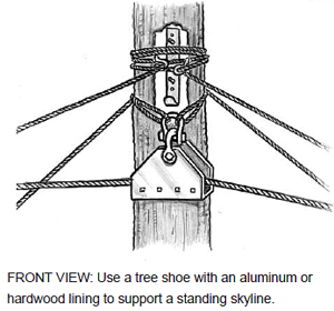 Keep straps as short as possible.
IMPORTANT: When using a tailtree to support the skyline, align the tailhold with the yarding road, no more than 8 degrees off a straight line back. Ideally, locate a tailhold a bit to the side to prevent the rigging from chafing the tailtree. If the tailhold needs to be outside of 8 degrees straight back, use extra guylines.
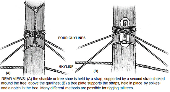
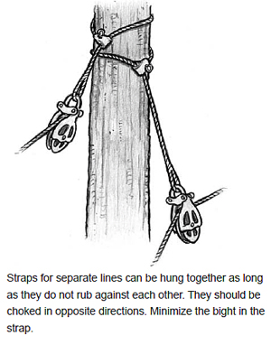
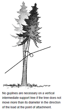
Support trees need to be assessed for strength and stability. The tree may not need any guylines, if it does not move more than its diameter at the point of attachment and the tree will not have the potential of striking workers. If the tree moves more than its diameter, or could reach a work area or haul road if pulled over, then it needs to be guyed to prevent failure. Use guylines of appropriate size and strength relative to the line in use (see table).
With uphill yarding, a tailtree may only require two guylines, positioned away from the yarder in the lower guyline zones. It is usually necessary to place all four guylines on a tailtree, especially when the tree is small, the rigging is high, significant side pull is exerted on the tree, or logging occurs behind the tree. Side pull occurs when the tailhold is more than eight degrees out of line with the yarding road, or when logging wider roads, larger than normal turns, or in a dutchman system that pulls the skyline to one side.
| Required Guyline Size for Tailtrees (inches) | |
|---|---|
| Line Size | Guyline Size |
| 5/8 and less | 3/8 |
| B etween 5/8 and 1 | 1/2 |
| 1+ | 5/8 |
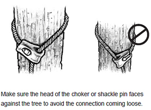
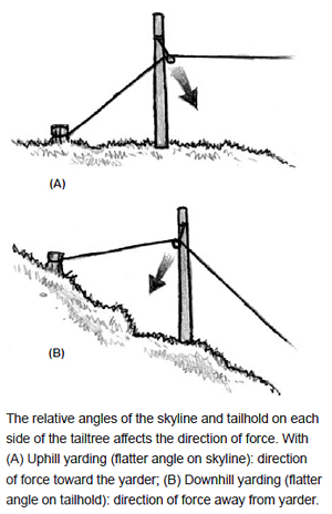
If logs are to be pulled from behind the tree, use four guylines. In a running skyline operation with both lines hung in a tailtree, use four guylines. If it becomes necessary to derig some of these guylines to facilitate the yarding process, make sure to account for the loss of stability. Never consider the skyline as a guyline.
Guylines should be positioned in appropriate guyline zones. If no stump anchor is available in a recommended guy zone, two guylines on either side of the guy zone can be rigged to oppose the load. Follow standard procedures to secure guyline anchors and use tiebacks and multiple anchors as necessary (see Chapter 4). Make sure the angles of the guylines as well as the skyline at the tailhold are no greater than 50 degrees from the horizontal.
Consider using buckle guys in a rigged tree when rigging produces a buckling force in the tree. Buckling forces are typically caused by extreme rigging height, undersized trees, or extreme side loading. Buckle guys are typically rigged at two-thirds the height of top guylines.
When placing guylines, pay special attention to the direction of force, which differs according to the relative angles of the skyline and tailhold on each side of the tailtree. The block strap will hang in the direction of force. In most situations, the force is toward the yarder, requiring guylines on the back side. However, when the angle of the skyline is narrower in front of the tailtree, as in downhill logging, the force will be backward and will require guylines in front (see diagram below).
IMPORTANT: Consult Division 7 or technical manuals for the appropriate guyline zones for different numbers of guylines. After rigging a tailtree, place a light turn on the load line to check that each guyline shares the load.
Rigged support trees create an additional hazard for the rigging crew. Workers must get clear of rigged trees before lines are tensioned: during outhaul and inhaul, and any time logs are moved or suspended, or any tightening of the running lines occurs. Minor movement of the rigging to set chokers does not require getting clear.
A competent person must instruct the crew on the boundaries of the failure zone for rigged trees and the direction of failure under different conditions. The force on a rigged tree is generally toward the yarder during inhaul, but the force can also be back, depending on line angles (see diagram), and possibly to the side, due to lateral forces. The direction of force will reverse during outhaul according to the position of the carriage and the pull on the jackline. Failure in a rigged tree can also involve the top snapping or the tree buckling below the point of attachment, which can send chunks flying anywhere.
Have a qualified person determine the failure zone of rigged trees, and notify the crew of this area and where it is safe to stand. Workers must stay clear of a potential failure zone of a rigged tree or other danger tree. Stay clear of the tree, and also clear of other trees, logs, lines, or other materials that could be struck and set in motion. Use extra caution when working in standing timber, where hang-ups are more common and forces exerted on rigged trees are more unpredictable.
A skyline supported by a block in an elevated support tree exerts different loads on the rigging and the tree in proportion to the interior angle of the skyline in the block. A sharper angle on the line running through the block will create more force on the strap holding the block. Use extra caution whenever lateral pull creates a sharp angle on a skyline in elevated rigging. Consider additional guylines and buckle guys, a larger strap, or reduced payload.
Tailtrees will probably require at least two guylines, and usually all four, to support the combination of forces on the tailtree during logging. The zone for the skyline anchor is within 8 degrees on either side of the yarding line. The guy zones for the tailtree are 35 degrees to 55 degrees offset from the yarding line. The two rear guylines usually take most of the load. Adjust guy zones according to the anchor offset, the position and strength of other guyline anchors, and lateral forces exerted on the skyline.
Intermediate supports are typically rigged midspan to provide lift over a ridge or hold the belly out of a long span. Jacks are typically rigged and the skyline rests in the jack, but is not secured to it, allowing the line to slide freely. A special carriage must be used that will pass over the jack.
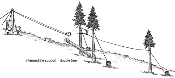
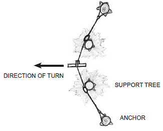
Overhead view of double-tree intermediate supports- shows guyline anchors positioned to counteract the yarding force applied to the hack in the direction of the turn.
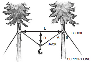
The two intermediate support trees must be rigged so vertical loading is distributed equally on both trees. Deflection in the jackline must be within a specific range corresponding to the distance between the two trees. Minimum: D = 1/4 L Maximum: D = 1/2 L O verhead view of double-tree intermediate supports – shows guyline anchors positioned to counteract the yarding force applied to the jack in the direction of the turn. Make the angle of the jackline from the block down to the jack (A) the same as the angle on the guyline down to the anchor (B). This will direct force downward. A greater angle on one side will force the tree to lean to one side and increase the risk of failure.
An intermediate support must allow horizontal clearance for the carriage and also allow a turn of logs to pass by the base of the tree. Three systems are available: a single tree, a leaning tree, or a double tree.
Double Tree. Rigging an intermediate support with two trees is the most favorable option, because it provides more capacity and also allows more space for a turn to pass by unobstructed. The jack must be rigged between the trees so the vertical load is imposed equally on each tree. Deflection in the jackline must be at least one-fourth, but less than one-half the distance between the two trees (see diagram preceding page). If additional guylines are needed, they are typically located straight back, away from the yarder, on each tree.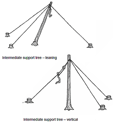
Leaning Tree. If a single tree does not allow enough clearance for the carriage to pass by the jack, or for a turn of logs to pass by the base of the tree, a leaning tree can be created by putting an undercut in the side of the tree where the lean is intended. Rig appropriate support guylines before making the first cut. Then make a backcut just enough to allow the proper lean, leaving at least 20 percent of the tree wood to keep the tree attached to the stump. The leaning‑tree support is much more complicated to set up and is not frequently used, though it does offer a solution in some instances for inadequate clearance on a single-tree support.
Single Tree. The single-tree support is the simplest to set up. A jackline is rigged in the support tree, with the jack either hanging free on the line, or anchored at an angle to hold the jack away from the tree.
For skylines larger than one inch in diameter, two guylines must be rigged; under one inch, one guyline can be used directly opposite the jackline. If the tree moves more than one time its diameter at the point of attachment, then a second guyline should be rigged 45 degrees downhill. If the tree shows no movement, no guylines may be required. On very small trees, where two guylines opposite the jackline are not adequate, use a third guyline in the direction of the jackline. If the tree still moves, use buckle guys, typically rigged at two-thirds the height of normal guylines.
IMPORTANT: Guyline anchors for support trees must be located within specific guy zones to offset the load, just as guyline anchors for the yarder tower. Pay close attention to anchor position and line angles.
Loggers are often required to climb considerable heights to top trees or hang rigging on lift trees. All workers exposed to fall hazards must be specifically trained and equipped for fall protection. The tree climbing rules summarized below also apply to other climbing conditions (see Div. 7, Sec. P).
Before rigging any tree, the employer must develop rescue procedures, along with appropriate equipment, personnel, and training to make a rescue in case a climber is injured or incapacitated in the tree. A second set of climbing gear and a person with climbing experience must be readily available. Use equipment and procedures that will support an injured climber’s chest and pelvis in an upright position during rescue. When an injured climber is wearing only a climbing belt, provisions must be made to prevent the climber from slipping through it; this can be as simple as using a rope to create an upper-body support system (consider replacing climbing belts with a climbing harness).
Check climbing equipment and immediately remove defective equipment from service. Make sure hardware closes securely before placing weight on the lanyard or life-support rope. Tie, dress, and set all climbing knots. Follow the cordage manufacturer’s recommendations on use of splices.
A climbing harness provides both pelvic and upper-body support, and may be a one-piece, full-body harness, or any two-piece design that meets industry standards. Climbing and life-support lines must be easily identifiable. All lines and webbing used for life support must have a minimum breaking strength of 5,400 pounds and be used only for climbing. When a cutting tool is used in a tree, the climbing rope (lanyard) must be a high-quality steel safety chain of 3/16-inch size or larger, or a wire-core rope.
Remove a life-support rope from climbing service when excessive wear or damage is detected and whenever it has been subjected to a shock load.
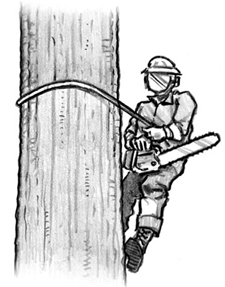 Many specific rules apply to climbing. Make sure climbers are well-trained in climbing and in the use of their equipment to carry out assigned tasks.
While climbing operations are active, co-workers on the ground must stay clear of potential falling objects. If co-workers must work directly below a climber, the climber must stop any activity where objects could be dropped or dislodged. The climber must give warning whenever any material is in danger of dropping or is dropped deliberately. Unsecured equipment, rigging, or material must not be left in the tree.
Yarding activity must cease within reach of a tree or guylines of a tree where a climber is working. Machinery may operate in reach of the climber to hoist rigging into the tree, in which case, a spotter is mandatory. Use extra caution.
Tree climbers generally use a three-point climbing system – three points of contact must be firmly in place on a secure surface before moving to another point. Along with hands and feet, other points on the body, such as a hooked knee, can be considered a point of contact if it can support the full body weight. In turn, the places of support must be secure; avoid unsound branches or stubs as a contact point. A lanyard around the tree secured to the safety harness or climbing belt on both ends counts as two points of contact.
Climbing without being secured to the tree is prohibited, except in conifers, when in the judgment of the qualified climber, the density of branches growing from the stem make attaching the lanyard more hazardous than simply climbing the tree. Attachment may be required farther up.
Only an experienced climber with experience felling trees should top a tree. Do not cut when wind or other conditions could be hazardous. Apply usual felling procedures, with a few additional steps as follows:
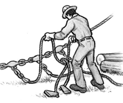
The hooktender is the person in charge of a yarding and loading crew. The designated foreman might also be the rigging slinger, yarder engineer, or another logger with many years of experience, but in all cases, it is important to assign specific responsibilities for safety to one supervisor in charge of the setting. The hooktender takes a lead role in laying out the setting and ensuring all equipment is in good condition, and is particularly responsible to remove or control hazards, communicate with the crew, supervise safe work practices, and know and enforce company and Oregon OSHA safety rules.
The yarder engineer operates the yarder and is directly responsible for its condition and operation. High proficiency should be expected from the person operating the powerful yarding machinery.
The chokersetter sets chokers on the logs for each turn and also assists in many other related duties.
The chaser works on the landing to unhook the logs, get rigging ready, limb and buck as necessary, and assist in keeping the landing clear of accumulated debris.
The yarder engineer operates the yarder and is directly responsible for its condition and operation. High proficiency should be expected from the person operating the powerful yarding machinery.
The loader operator grapples and decks logs, and loads log trucks. The loader is the most mobile machinery on the landing and the operator must be constantly alert to ensure safe clearance from the yarder and workers on the ground.
The processor operator grapples logs from the landing chute and cuts them to length. The processor can use a lot of space on the landing.
Before yarding begins, the hooktender should be satisfied that hazards are controlled and the crew is ready to operate. The necessary equipment safety inspection (outlined in Chapter 3) can be performed by the hooktender or another competent person, or others working under their supervision as the setup proceeds. The hooktender must also pay particular attention to the following conditions:
Clear hazardous terrain and conditions. Yarding usually begins on the upper side of the unit closest to the yarder, so the crew remains above any hazardous logs, rocks, and other debris on sloping ground. Reassess the terrain for hazards as the crew moves downhill. The hooktender or rigging slinger must be sure the areas above the rigging crew on a slope are clear of any materials that could roll or become dislodged during logging activities. Whenever possible, the hooktender should stay with the rigging crew in difficult terrain to help identify and control hazards.
Stay aware of danger trees. Arrange work to minimize danger to workers. Snags and other danger trees within reach of the landing must be removed if they could endanger the landing crew (see Chapter 2). The rigging crew must be aware of any danger trees throughout the work area, and must follow up to prevent the crew’s exposure to hazards.
Communicate with the crew. The hooktender needs to discuss and involve the crew in planning and setting up safe work procedures to keep them informed. The hooktender must know the capability of each worker under his supervision and must not give a worker a task if he doubts the worker can do it safely. Any person giving instructions must be satisfied that the worker fully understands and can carry out the duties safely. Work activity and coordination should be regularly communicated by the hooktender to and among the rigging crew. The crew should be continually reminded to stay alert.
IMPORTANT: All workers, and lead workers in particular, should make an effort to share their knowledge with co-workers to help everyone work more efficiently and safely.
Use caution when working above the landing. Downhill yarding may cause timber and other objects to run down a slope and endanger ground personnel. Arrange work activity so the loader, processor, and yarder operators are not in danger, and establish a safe work area for ground personnel.
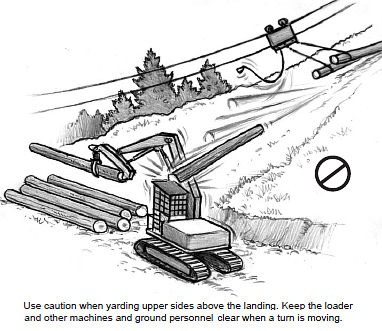
Safe yarder operating procedures can prevent serious injuries to work crews on the ground as well as to the operator. It is extremely important to incorporate the following general safety guidelines for yarder operation:
Check brakes and guylines first
At the start of each shift, machine operators must test all drum brakes and check guyline tension before taking a load.
Establish a signal system. All line movement must be directed by a signal. Audible signals must be given by the rigging crew before any action is taken by the operator. Hand signals or other procedures can be agreed upon in advance in situations where the operator can clearly see all the activities of the rigging crew and has a clear view of the chaser on the landing. If the yarder engineer gets commands, he must sound the whistle before any line is moved or stopped. If a voice or whistle signal is not clearly understood, the operator must not take action until the signal is confirmed. The yarder operator is best positioned with an overall view and may notice dangers that the crew cannot see. Establish a signal system to allow the operator to warn the rigging crew of running logs, rocks, or other materials on a slope. All operators must have a plan to communicate if a log goes over the edge.
Clear the lines. Before yarding commences, tightline the skyline, mainline, and/or haulback to clear out any siwashes or limbs interfering with the lines on the back end of unit. Recheck all anchors.
Monitor guyline anchors. While yarding, the yarder operator must always be aware of the guyline arrangement and make sure that guylines oppose the yarding forces and share the load. The operator should also be alert for any unusual movement of the tower due to stump lift or lead change. Immediately report any observed movement in the guyline anchors to the hooktender for correction.
Spool lines properly. Lines should be spooled and tightened properly onto the drums when they are first installed and be kept properly spooled for line life. Upend the lines regularly to reduce excessive wear and increase the life of the line. Poorly spooled lines can damage the lines, increase the chance of a break, and cause uneven slack during heavy loading. All lines should be run in at a very slow speed when workers spool the lines. Workers wearing caulked boots are not allowed to stand on metal covers or hoods while they spool lines, unless the metal is covered with a nonslip material.
IMPORTANT: Workers should use proper spooling irons or tools when spooling the haulback and mainline so they are not caught by any jaggers on the lines.
Stay alert at controls. The yarder operator must remain at the controls when the crew is working around the rigging and stay alert for accidental line movement or other hazards that could affect the crew.
Set the brakes on rigging. When turns are being set, the yarder engineer must stop the drum and set the brakes. If using a slack-pulling carriage (MSP), it may be necessary to leave the mainline brake off.
If the brake system fails or the brake controls are released by accident, the rigging can drop and injure the rigging crew. Following are the most common sources of failure:
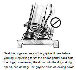 Avoid reefing. Reefing at full power adds stress to the rigging and equipment, and can cause worn or weakened parts to fail or cause the turn and rigging to react violently. Develop line pull in moderation, relative to the ground conditions and timber being yarded. Operators should know how much line pull is applied when operating the yarder at maximum capacity and ensure the force developed during operation does not exceed the capacity of the stump anchors and yarder tower.
Seat the dogs. Dogs must be positioned and the guyline drums gently set back onto the dogs before yarding operations begin. Not seating the dogs properly can cause excessive strain on the guyline drum mechanisms and may lead to drum-shaft failure and, in some cases, tower failure.
Assure cab guards and exits. Make sure all guards are adequate and properly maintained on the operator cab windows and covering gears, belts, and chain drives. Keep all doors to the cab closed during operation. Check that an alternate exit is available and functional in case of emergency.
Using whistles, the rigging slinger directs the movement of the rigging and choking of the logs. The rigging slinger needs to keep a sharp eye out for unstable logs or objects and alert the crew to specific hazards that develop during the yarding process.
Always work from the top of a hill to the bottom so work never occurs below unlogged areas. Usually, yarding operations begin near the landing and work toward the back end. Extra caution is required until yarding activity is clear of the landing and guylines, where the close working conditions increase hazards.
Only one worker can give signals or voice communication to move the rigging. Any person in the crew is authorized to give a stop signal in an emergency situation. If the rigging slinger is also the hooktender and must leave to perform other tasks, a qualified chokersetter must be designated with supervision and communication responsibilities for the crew in the interim.
Knowledge of the following basic work procedures related to the rigging crew is essential to avoid injury and maintain effective production.
Stay alert for hazards The rigging slinger needs to keep a sharp eye out for unstable logs or objects and alert the crew of specific hazards in each setting.
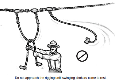
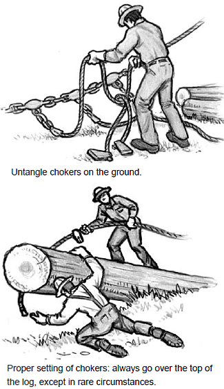 The rigging slinger will select the turn and spot the rigging, and tell the chokersetters which logs to choke. Effective communication and teamwork among crew members is critical. The following main points about setting chokers affect the rigging slinger’s selection:
The following additional procedures apply when using a drift carriage or buttrigging:
IMPORTANT: Beware of too much slack in the line. With multi-speed carriages, it is possible to feed out the lines too quickly. Excess slack can push the crew too fast through the brush, or worse, can coil into a tangle and snap back when moved.
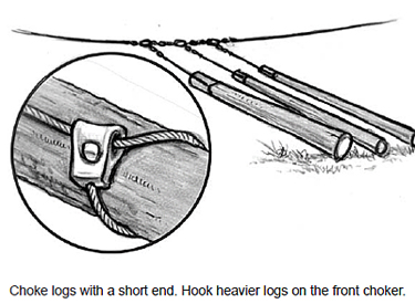
Pre-setting chokers decreases the yarding cycle time by allowing workers to set chokers while the turn is being yarded. Some logging crews use a method called “swedging” – splitting up the crew into two teams with one set working the front end of the logging road and the second set working the back end. They use three sets of chokers. One team can pre-set chokers while the other is moving a turn as long as they remain in the clear of the rigging. Observe the following precautions in any procedure pre-setting chokers:
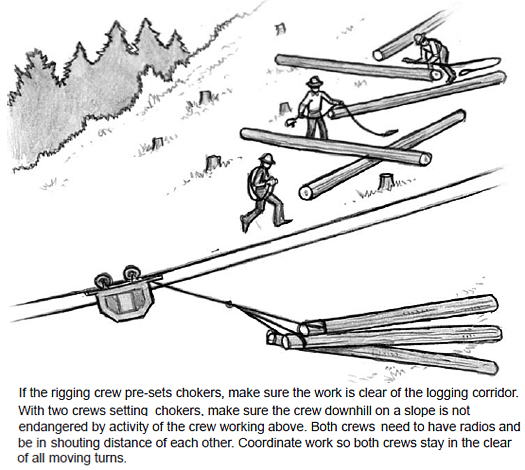
IMPORTANT: Never touch a moving line with any part of the body; do not ride moving hooks, lines, or logs, or use a moving cable as an assist when walking uphill.
Certain logs may require special treatment. In some instances it may be necessary to use more than one choker to move a log. Three alternative hitches are commonly used:
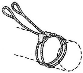
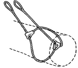
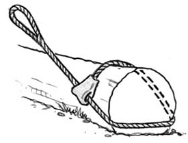
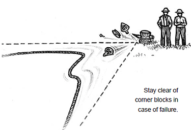 Get in the Clear
 Once the chokers are set, the rigging crew must get in the clear before the go-ahead whistle is blown by the rigging slinger. Always get in clear before lines begin to move. Never touch a moving line.
When the rigging crew is in the clear, the rigging slinger blows a go-ahead signal, and the crew must watch the turn until it is yarded free. Blow a “go-ahead-slow” signal if there is any question about the turn, such as length or action of the logs in the turn. Watch for debris picked up by the logs or rigging that could roll back at the crew.
With signals to the yarder engineer, the rigging slinger controls the speed on the mainline and how fast the carriage pulls in at the same time. The drop line needs to pick up fast enough to avoid hang-ups that could break a choker and send a log back down the hill; never allow suspended logs to overhang the crew. Consider how long to leave the dropline out of the bottom of the carriage. A longer drop line can cause hang-ups and difficulty landing the turn.
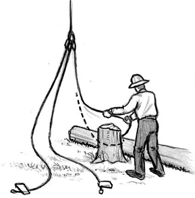 Hang-ups
The best way to clear a hang-up is to reposition the carriage or choker to avoid the obstacle. Other techniques are possible, including the jump, kick, or roll (see diagrams). If these options do not work, the hooktender or rigging slinger is generally the person who “fights” a hang-up. Signal to stop the turn, and slack the rigging before approaching the hang-up. Always approach a hang-up from the upper side and stay alert for hazards.
Repositioning the rigging can direct yarding forces to overcome obstacles. The jump, kick, and roll are common solutions.
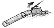
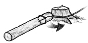
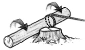
Work rules for hang-ups
Only approach a hang-up after the rigging has been slacked. Approach from above the hang-up and be alert for the danger of logs rolling or sliding, widowmakers, and danger trees.
Always Know Your Escape Route
Major hazards for the rigging crew discussed on the following pages represent specific conditions where specific safety recommendations apply. In addition, workers in the brush need one good tip that applies everywhere:
STAY ALERT AND ALWAYS KNOW YOUR ESCAPE ROUTE.
Train new workers to keep an eye out for hazards while they work and think through in advance which way to move if danger erupts. A work position with no good escape route is probably the wrong place to be.
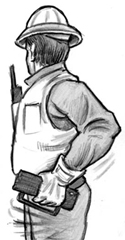 Unexpected line movement can result if a radio signal malfunctions or is used wrongly. Check equipment and operator knowledge of signals in advance.
Always have two radio transmitters where chokers are being set. A second radio is for backup, but there could be occasions when the second radio is used to stop the rigging when the rigging slinger is occupied or when the crew splits up to set chokers on either side of the mainline. Alert the yarder engineer when both radios are in use.
Precautions
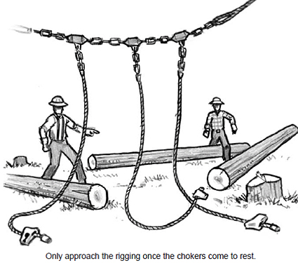 Avoid chokers when the line is moving. Foremost, stay clear of swinging chokers when the rigging is suspended. Chokers dragging on the ground with line movement can also be dangerous if they catch on an obstacle and spring free.
When grabbing the chokers directly under the carriage, either run the carriage ahead or get in and get out, particularly when the carriage is low to the ground.
Precautions
Use caution when working directly under the rigging. There is always a chance a line will be unintentionally released and rigging will drop faster than expected when being slacked down.
Suspended rigging can be dangerous. When the rigging is slacked down, any part of the lines can hang up on saplings or windfall roots and dangle dangerously. Always clear hang-ups before choking logs.
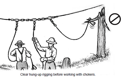 Precautions
Suspended rigging hazards
- Drum brakes can fail.
- Brake bands, anchors, adjusting rods can fail; ratchets may slip off pawls, particularly on early-model yarders.
- Sudden loss of air pressure can cause the rigging to drop some distance before the spring brake or dogs engage.
- Controls may be accidentally released.
- Brake may be wet or sticky.
- Rigging may hang up on limbs or roots and crash down unexpectedly.
- The skyline can incur bounce when the rigging is stopped fast.
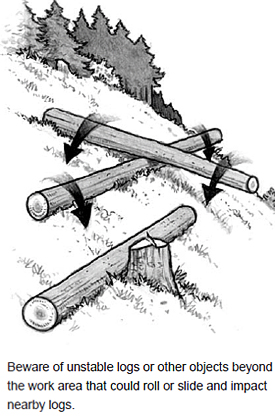 Gravity is the primary source of hazardous energy when working on a slope. Logs, rocks, or other objects can be disturbed by rigging activities and roll or slide downhill toward the crew. The risk is greater working around newly felled timber, where logs can shift and dislodge other logs or material that appeared stable.
Precautions
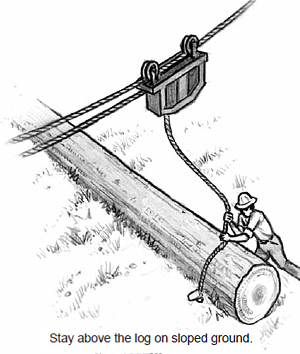
Be prepared
Always know your escape route!
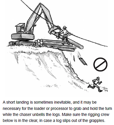 The landing must be planned to minimize the risk of logs or other debris kicked loose at the landing from running downhill toward the rigging crew. On a small landing, the cramped operating area for the loader becomes hazardous: a log in the grapple can strike the mainline and cause the rigging to jump as the rigging crew sets a turn below, or logs may be decked too close to an edge and get disrupted as logs are added.
Precautions
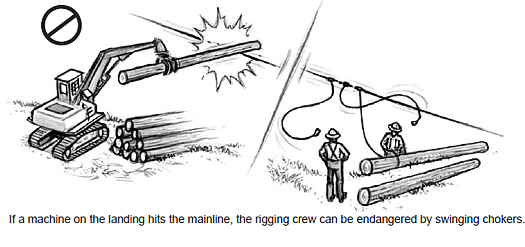
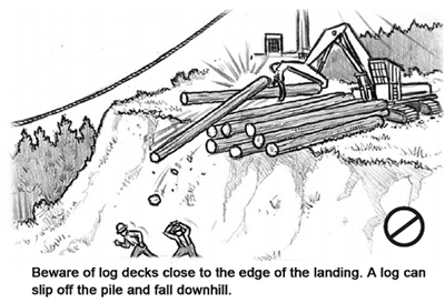
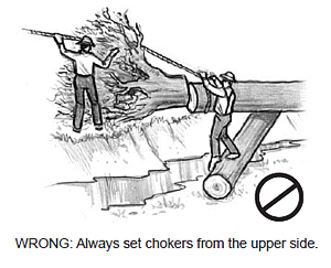 Windfall roots will often sit back when a tree is bucked off or yarded free, particularly if it is bucked short. Heavy rains can disturb the ground and this may cause the root to tip more easily.
Unstable rootwads, when kicked loose, can move unpredictably and cover a wide swath. Any unstable rootwad identified as a hazard in a work area needs to be moved or made secure.
Precautions
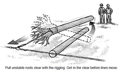
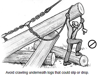 Hooking up the turn and starting it to the landing can be hazardous work. Adequate training and safe work procedures are vital. In addition to the safe practices outlined earlier in this chapter, remember the following general precautions:
Precautions
On a steep hillside, if the haulback is slacked too much or runs unexpectedly when setting the turn, logs already hooked up can be pulled downhill by the weight of the mainline.
Precautions
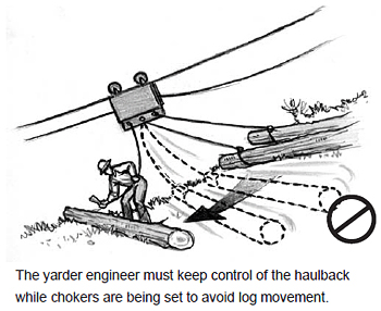
Adding a string out to a choker or leaving a long dropline can be useful to reach a distant log or direct a log around an obstacle. Tags should be removed and droplines shortened before the turn is yarded to the landing. Strung-out logs foul more readily and are more difficult to control and tightline clear. Strung-out logs are also more difficult to land and may run outside the turn and jill-poke other logs ahead on a pile.
Precautions
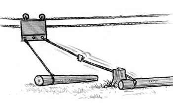
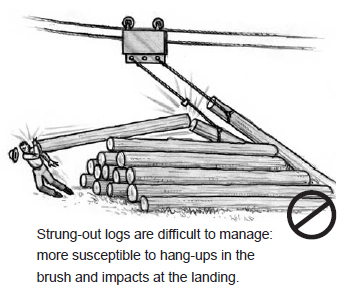
IMPORTANT: Untag logs in a safe area where logs are stable and not likely to move.
Once a turn starts to move, a hang-up can cause a log in the turn to swing or upend, even when the logs are properly choked and there is good deflection in the line. The risk of a swinging log increases when logs are choked with long ends or guthooked, and with a ground lead.
Long ends give a log greater potential to upend or swing violently if it comes in contact with a stump or hang-up. This is most dangerous with long logs or tree-length logs, which have a greater swing radius.
Precautions
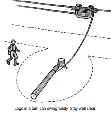
The rigging crew must always get clear before a turn moves. Loggers standing in the bight of the line risk contact with a whipping cable, choked log, or thrown debris. Avoid a layout with a large bight area. A poor layout can make it difficult for the crew to get in the clear or judge where it is clear, especially near the front end.
Precautions
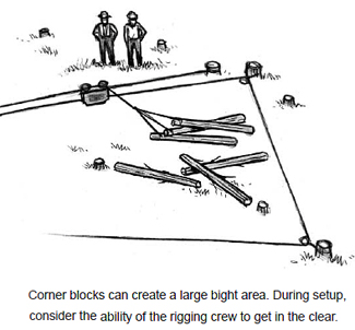
Releasing a line off a stump anchor is very hazardous, due to pressure in the line. Use caution and always stand on the inside of the point of attachment during release, particularly when there is pressure in the line.
Stumps are either wrapped once and attached with a shackle through an eye, or they are wrapped three times and cable clipped or spiked. With single-wrapped stumps, it may be safe enough to unhook the end of the line and let it run. If the line needs to be held on the hillside, use a rigging chain and a short strap, or use a catch shackle and strap.
With multi-wrapped stumps, it may be necessary to use a rigging chain and use the haywire or come-a-long to pull the pressure out of the line in order to release the stump. If the pressure is great, use a back wrap to ensure the line is all out in the direction of pull, and use the haywire or come-a-long to lower the line.
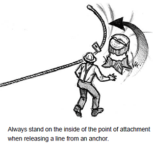
Beware of the increased risk of a choker breaking when yarding across a hill where the turn cannot be held from running through felled and bucked timber. Tightlining the rigging to clear the obstruction increases the danger of rigging flying uphill toward a crew “in the clear” if a choker or other rigging fails.
Precautions
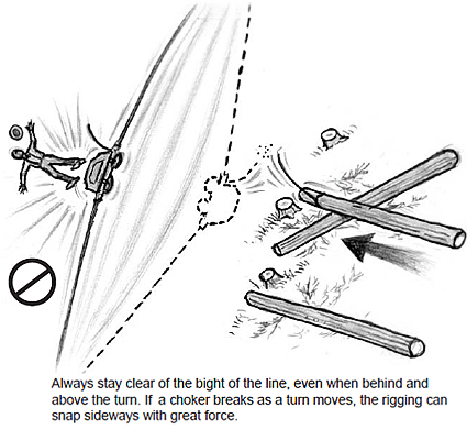
Avoid heavy turns
Turns that are too heavy or hooked up improperly increase the chance for hang-ups. Reefing and heavy pulling strain the rigging and tower, and may result in catastrophic failure.
Select turns light enough to yard without reefing.
Hang-ups are always hazardous. Good planning for the landing, yarding system, road lines, and payload should minimize problems with obstructions. Every hang-up is going to be different. On some it may work to dislodge the hang-up by repositioning the carriage and pulling in the opposite direction. Others may require unhooking the logs and repositioning the chokers; and others to pull out one log at a time. Avoid letting hang‑ups become routine, which may encourage the crew to gradually stand closer to the turn and forget the risk.
Precautions
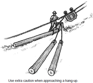
Hang-up Hazards
ALWAYS INSPECT A Hang-up CLOSELY FOR HAZARDS!
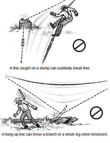 Remove snags and danger trees in the area before work begins (see Chapter 2), or arrange work to limit exposure. Stay vigilant as work progresses and report hazards to the hooktender.
Danger trees from farther away can also be hazardous if caught in the path of a tightening line. A siwashed line caught on a tree, rock, stump, or debris pile can throw materials a considerable distance, and the bight in the line can spring one direction and rebound opposite if it breaks free. Siwashes also rapidly damage a line and can be a fire hazard in dry weather.
Pay close attention to line movement to indicate obstructions. A haulback that saws into a stump, for example, will not move freely and may develop slack in the backline that allows rigging movement even after the yarder stops. If the rigging does not move at once when the haulback is slacked, stay clear and slowly pick up the slack, then look for a siwash.
Precautions
Haywire Siwashes
Haywire hazards are commonly underestimated. The small line is actually more dangerous than other lines, because it more easily runs through and catches on obstructions, and more easily breaks free under tension. Haywire can fail and throw pieces. Always stay clear of the haywire just like other moving lines, and watch carefully for siwashes.
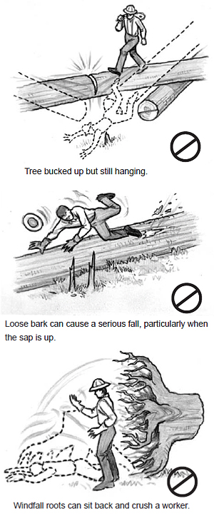 Hazard 16. WALKING IN FELLED TIMBER
Walking in felled timber presents several hazards, even on level ground. Logs may be unstable or slick, with bucked sections, or loose bark, and falling even a short distance off a small log can result in serious injury, due to sharp branches, broken hinge wood on stumps, uneven surfaces, stubs, or other hazards.
In an area of newly felled timber, snags or wildlife trees may have been left, and loose limbs (widowmakers) may remain along the cutting line. Root wads bucked short have been known to suddenly sit back upright. Avoid walking under roots and stay alert for other hazards.
Precautions
Working in a thinning operation in standing timber poses additional risks for the rigging crew not normally encountered in a clearcut unit. Workers need to contend with leaning and hung trees, limbs, and other overhead hazards, spring-loaded limbs and vines, logs that are out of lead, logs that will not easily turn up the corridor, and similar obstructions due to surrounding trees left standing.
Two of the biggest risks involve intermediate lift trees. Rigged trees can fail and fall in an unexpected direction, or the carriage can jump off of the jack as the carriage is returned to the rigging crew. Make sure the crew stays out of the potential failure zone of rigged support trees during outhaul as well as inhaul.
Trees or logs felled in a thinning operation may lay out of lead, making it necessary to position the carriage with some care to provide the straightest pull out to the corridor without a hang-up. As the turn is pulled to the corridor, it may be necessary to reposition the carriage again to overcome a potential hang-up. The rigging slinger needs stay alert to stop the inhaul of the drop line before a turn becomes hung up.
The way logs are choked can help avoid hang-ups. Consider choking logs farther from the end than normal if it appears the pull will help a log clear a hang-up and enter the corridor before it swings into the direction of pull. Once the log is free, it may be necessary to stop and adjust the choker to the end before sending the turn on to the landing.
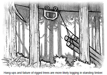
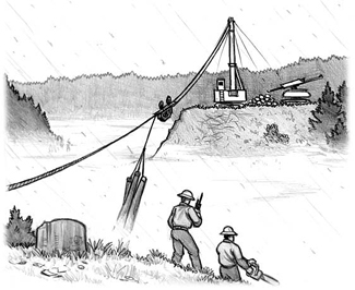 Poor weather creates hazards in the environment and also affects worker attitudes and energy. Cold and wet workers will be less vigilant and less likely to move far enough into the clear. Make sure workers dress appropriately for the weather to stay warm and dry.
The following points cover common conditions:
Rain
Fog
Work can be carried out safely in fog by organizing additional communication and other precautions. However, on steep ground, work must stop if crews cannot see runaway objects. Wait for vision to improve.
Snow
Yarding in heavy snow is not always safe, practical, or productive. Workers must be extremely cautious. Activity is slow and workers are prone to slips and falls. Logs can slide more easily, farther, faster, and quieter on snowy slopes.
Light snow produces hazards for the rigging crew as well. In moderate conditions, though, it may remain possible to load trucks on the landing. Use extra caution when getting on and off machines and trucks. Use tire chains when necessary.
Thunderstorms
Lightning does indeed regularly strike poor souls working outside in the rain. Electrical storms are particularly dangerous for loggers. Nearby trees attract lightning; so do long lengths of steel cable, and especially moving cables. The risk is much more real than commonly imagined.
Hot and Dry
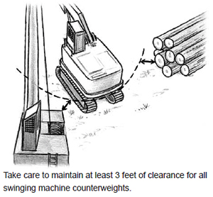 Good planning of the yarding and loading setup and preparation of the crew removes numerous hazards. Once set to begin, confirm safe zones of operation for the machinery, confirm radio and signal transmissions, and confirm that everyone knows and understands the signals and operating procedures. Teamwork among the entire crew is essential for both productivity and safety.
The landing crew usually consists of four basic positions: yarder engineer, chaser, processor operator, and loader operator. Other workers that could be on-site include log truck drivers, and, in some cases, a hooktender, log graders, landing buckers, traffic control, maintenance, and other workers.
All workers on the landing must have a designated safe position outside machinery working areas and be visible to machine operators. During operation, observe the following primary rules:
Machines may only be started and operated by authorized personnel. Operators must know the manufacturer’s operating instructions, as well as safe work practices and site procedures. An inexperienced operator can cause danger to other workers and damage to the equipment. On-the-job training with a specific machine is necessary to develop proficiency. State licensing is not required. Employers must decide for themselves when an operator is qualified to safely operate the machinery.
Training newer workers in appropriate situations should be a continuous process. Employers must keep a current written record of job safety training for each worker. This record can be used as a training tool.
The chaser unhooks turns coming to the landing, keeps the landing area clear of accumulated debris, uses a chainsaw to limb and buck logs, and monitors the safe operating zones of machinery to ensure a 3-foot clearance. Due to the hazardous working environment, the chaser wears high-visibility clothing or hardhat, and must stay constantly vigilant and careful of the position and movement of machines.
When the chaser leaves the landing for any reason, operators should be told when he goes and when he arrives back. Operators must not move or handle logs without seeing or knowing the chaser and other ground personnel are safe. The loader operator must ensure that log truck drivers and others who may enter the landing are aware of hazard areas and safe procedures.
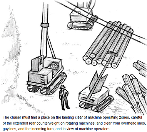
Unsafe Locations on the Landing
Underneath or near the mainline during the yarding. The mainline and haulback could break and drop, or the mainline could be slackened accidentally without warning.
Underneath the guylines opposing the pull of the turn. Avoid working under the active guylines in case of anchor or line failure. Stay aware of the yarding process while moving about the landing as a turn in a new position can shift the load to different anchors. Be aware of any known weak anchors.
Within reach of the turn being landed. The area within reach of the incoming turn is directly hazardous, and a farther area is indirectly hazardous. Beware of other logs already on the landing within reach of the turn. Logs entering the landing can jill-poke other logs and upend, swing, or push them. Choked logs with a long end increase the hazard.
Working in the blind spot of machinery operators. The chaser needs to ensure that the machinery operators know when he needs to enter a blind spot to perform any task.
Within the swing of the loader, processor, or swing yarder. Never approach the loader or a swing yarder without the operator’s acknowledgement. To approach within 3 feet, the machine must stop. These machines are particularly hazardous because of the swinging counterweight on the rear that often takes workers by surprise, and also, the broad sweep required to swing logs onto decks and trucks. A rotating machine must maintain a minimum clearance of 3 feet for the counterweight in all directions.
Regularly check how lines are spooling onto the yarder drums. New lines in particular tend to unwind in use and can cause spooling problems. Incorrect spooling can crush the bottom layers of line as more line is added. If spooling is a problem, first check the level of the yarder base and tower. Adjusting to plumb can solve the problem. In some cases it may be necessary to completely respool a line. Snub the line and use a soft hammer to tighten each wrap as the line spools.
Turns are generally landed in the area immediately in front of the yarder (the chute). A swing yarder is an exception, swinging the turn to the side. In all cases, the yarder engineer must stay alert that ground personnel remain in the clear and regard the safety of any workers positioned downhill from the landing area. Some operators allow the chaser to operate the carriage bug, working closely with the yarder engineer to land the turns. Loaders and skidders used to clear the chute must remain in the clear while a turn is landed.
The slope of the landing chute must be less than 20 percent if a chaser is required to unhook the rigging from the logs or when a rigging crew is working immediately below the landing. A chute slope more than 20 percent may require a grapple to assist in securing the turn. Additional control measures are also possible. Haywire can be used to control logs from rolling off the landing.
Machine operators must always use extreme caution when the rigging crew is working below the landing and avoid knocking material over the edge. Stack log decks carefully to ensure stability. Rolling logs or sliding poles can travel a considerable distance downhill.
The yarder engineer must be careful to control the turn being landed and use the assistance of other machinery on difficult turns. The yarder engineer must also ensure the chaser is not in the landing chute or in front of the yarder when landing turns. Use the following procedures to make unhooking the turn easy and safe.
Slow the turn before it approaches the landing. Tightline or slack the lines as required to safely land the turn. Avoid striking the ends of decked logs.
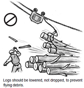 When available, use the haulback to help control turns. If the haulback is not sufficiently snubbed when landing the turn, the turn could be yarded into the tower or could kick other logs ahead into the yarder. On steep approaches, it may be necessary to slack the haulback when near the landing and let the logs slide a short distance into the landing. If the haulback is braked too much, the turn could tightline or “balloon,” causing the ends of the logs to swing in all directions, creating a serious hazard.
Lower the logs. Chunks of debris can be thrown great distances when a load is dropped. If it is necessary to purposely drop a turn to stabilize a pile, make sure ground personnel are well in the clear.
Do not land or deck logs in a crisscross manner or in unstable piles. Unstable piles are hazardous to the chaser and workers below the landing.
Use extra caution on guthooked logs. Guthooked logs are more difficult to land safely. Lift as high as possible on approach to clear the ground and any previously landed logs.
Use caution with heavy turns. On some older yarders, it may be necessary to stop heavy turns just before reaching the landing. Release friction and apply again with only sufficient pressure to land the turn.
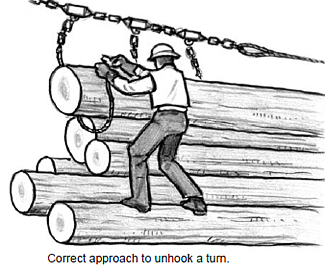 Once a turn is landed in the chute, slack the rigging only enough to unhook the chokers. The rigging must be completely stopped and the logs stable before the chaser approaches. Both the operator and chaser should re-evaluate the stability of the turn as the chaser approaches. If any logs appear insecure, the chaser must retreat to a safe spot, then signal for the turn to be picked up and repositioned by the machine operator. The operator must receive a signal from the chaser before any lines are moved.
The chaser must follow safe procedures.
At times the loader or processor operator may be signaled to lift a log to free a fouled choker or to reposition an unstable log. Always use machinery to clear a fouled choker. Many workers have been injured when logs rolled on them as they tried to free a fouled choker. Machine operators must coordinate with the chaser before swinging the boom or grapple into the area. The chaser should signal to the yarder and other operators how many logs are left to be unhooked.
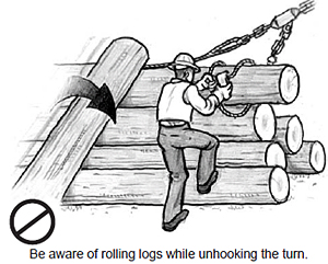
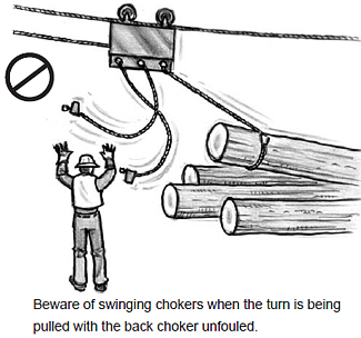
Logs must not be permitted to accumulate in the landing chute to the point where they become a hazard. The landing chute should be cleared of logs before the next turn of logs is landed, unless the logs are fully contained in the chute or there is no possibility that workers below the landing are endangered. The chaser coordinates with the loader operator to clear the chute of accumulated slash and debris before the next turn.
The shovel and processor operators also keep the landing area clear of accumulated debris. A safe debris pile should be established where workers below the landing will not be endangered.
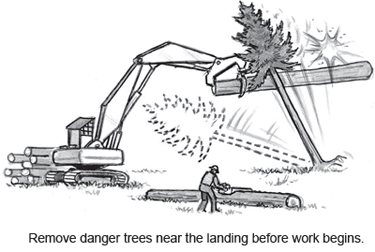 Hazard 1. DANGER TREES
Danger trees within reach of the landing must be felled before yarding begins if they pose a hazard (see Chapter 2). Stay alert during operations to be sure no other trees or saplings have become a danger.
The chaser is in the most danger of being struck by saplings pulled over into the landing by the moving turn or swinging logs in the grapple of the log loader. The tops of trees can break off and fly in any direction.
Precautions
In downhill yarding setups, yarding is not allowed if the yarder engineer is endangered by sliding objects. Straight downhill yarding on steep slopes is particularly dangerous. Typically, a larger landing area is needed to increase the amount of space in the clear. Logs can come to the landing out of control at times.
Plan in advance how to work on steep slopes and take measures to minimize the risk of logs or other debris rolling into machinery or ground personnel. The machine operator and a competent person must agree how to safely operate, considering experience of the operator, machine limits, soil conditions, corridor directions, hazards of moving machinery, weather, load size, and any other adverse conditions.
Precautions
When the yarder needs to be moved to a new position on the landing, the tower must generally be lowered first. The tower may be raised for mobility if adequately supported and the stability of the machine is not impaired. Be careful on rough ground to avoid damage to the tower from flexing in the carrier saddle.
Moving the tower and raising it again on new guylines can be a hazardous moment. Ensure workers are aware of the danger and alert to potential failure.
Precautions
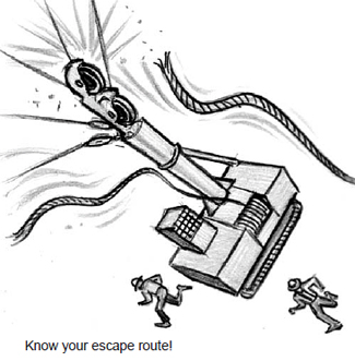 Wire rope most often fails because it is worn out or overloaded. Planning, equipment inspection, and safe operating procedures are the best way to prevent line failure. Follow out-of-service requirements in Division 7.
Lines generally break in the leads where they twist through sheaves. Whenever a line breaks, movement is likely to occur around the landing.
Chasers must remain far enough in the clear to avoid being struck if lines do break and fall. Beware of thrown objects that may come with a broken line, such as parts of blocks or shackles; and beware of the possibility the tower could collapse.
Chasers and ground personnel need to plan escape routes in advance to know immediately where to go if lines fail and come crashing down.
The cab of the yarder must protect the operator from broken lines, chunks, and logs. Shear or deflector guarding must be installed in front and the sides of each cab to deflect whipping saplings and branches without compromising visibility. Every fully enclosed cab must have a second, alternate means of escape without tools.
Most cabs must provide structural protection and restraint for the operator, including ROPS, FOPS, reinforced cabs, or overhead guards. Operators of stationary yarders are not required to use the operator restraint system or wear a hardhat while working in the cab. See Division 7 for specific requirements.
Maintenance
Guarding is particularly important during and following maintenance. Do not run the machine during maintenance with guards removed, unless necessary for a particular procedure. Completely shut down and lock out energy during maintenance.
Unless provided for by the manufacturer, never start a machine from outside the operator’s cab – something commonly but wrongly done during maintenance, which puts the operator at risk outside the guarded space of the cab. Sudden movement of a parked machine or vehicle can be fatal. Start and operate machines only from the operator’s seat.
Machines must not be operated until all guards are reinstalled, safety devices reactivated, and maintenance equipment removed after adjustments or repairs are made. Without guards in place, the operator or others may be caught in gears, or belt and chain drives. These are almost always severe or fatal injuries.
Precautions
All lines need to be spooled at one time or another. Guylines and the skyline are the most common lines to need attention.
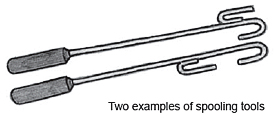 Use caution walking and working on metal yarder surfaces. Caulk boots are not safe, unless a nonslip material covers the walking surface. Stand securely with both feet on the platform, and do not rest a foot on or near the drum or any moving parts.
Assure all guards are in place to avoid contact with hazardous pinch or shear points. If it is necessary for a worker to stand near the drum to spool a line or perform machine maintenance, make sure hazardous energy is shut down and locked out to prevent unintentional activation of the drum.
Always use an appropriate tool. It is OK to touch a moving line provided it is moving slowly. Use a handover- hand motion. Do not allow a line to slide through gloved hands – a jagger can catch on the glove or hand.
Haywire is most commonly used when stringing guylines and changing roads. Siwashes are not as common or severe on the landing as in the brush, but the landing crew is also at risk. Pay close attention to line movement to indicate obstructions. Notify the hooktender immediately if a hazard emerges, and clear any hang-ups before continuing.
(See more on haywire safety in Chapter 5, stringing the guylines, and in Chapter 7, Hazard 14 on siwashes.)
When working the landing, the yarder engineer must ensure the chaser is out of the bight of the line before any line is moved. A particular hazard exists when sending signals to a radio-controlled carriage. It is possible for the carriage to get the wrong signal or the operator to hit the wrong switch, and have the carriage react unexpectedly. The chaser needs to stay alert to whistle signals that indicate a line is about to move. When removing or placing the carriage on the skyline, be sure the carriage is properly supported so it does not fall on workers.
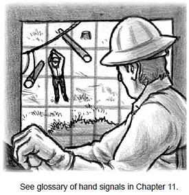 Chasers must understand and correctly use hand signals to avoid injury from unexpected machine movement. The chaser and machine operators must understand when and where hand signals will be used, with a set of mutually understood signals.
Ground personnel and machine operators must coordinate their activities to avoid dangerous situations. The chaser or other person on the ground must stay visible while machinery operates. Make distinct hand signals within a visible distance, but beyond reach of the machine. Be certain the operator understands the signal before moving.
Precautions
Unhooking the turn requires good physical condition, quick reflexes, and rapid judgement of hazards in the situation. Chasers need to be fit and sharp.
Follow safe practices described earlier in this chapter. Stay alert for the kinds of hazards experienced by the rigging crew: avoid working from the lower side, avoid unstable logs, watch for counterbalance swing, avoid working directly under the rigging, and stay alert for unexpected hazards.
If any logs in the turn arrive on strung-out chokers or a long dropline, stay clear of logs already on the landing that could be disrupted.
IMPORTANT: Watch for long ends of logs, mis-choked logs, and logs or trees coming into the landing at odd angles.
Communicate!
The chaser needs to communicate to the machine operators any intentions to move out of the normal, clearly visible safe position on the landing. Always notify operators when approaching the turn, moving to buck logs, or any other activity.
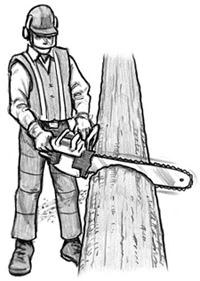 At some operations, chasers must use a chainsaw continuously. Chasers must be trained in safe handling and use of a chainsaw and wear proper personal protective equipment, including leg, eye, and ear protection.
A particular area should be reserved on the landing where bucking can be performed safely. Stay in view of the machine operators on the landing and make sure they are aware of the work being performed.
Use caution when working on log piles. If a log is unstable, the log loader or processor can move it to a safe position. Stay in the clear when logs are moved.
Do not brand, buck, or trim logs in a location exposed to contact with moving lines, logs, rigging, machines, equipment, or vehicles. Use extra caution to avoid the mainline when working in the chute.
Many workers are seriously or fatally injured in work areas that combine vehicle and machine traffic and ground personnel. Instances include riding on a machine outside the cab, approaching or trying to mount a moving machine, and getting caught by a vehicle or machine backing up.
Parked vehicles can be a hazard as well. Many workers are injured while working around or under a stationary vehicle that suddenly moves.
Working machines can suddenly and unexpectedly move. Always consider the path of travel, swing radius, or blind spots of all machinery, even when stationary.
Precautions
Trips and falls are common, but often preventable. Wear caulked boots if work involves walking on logs. Note that caulked boots easily slip on metal surfaces. Step carefully mounting or dismounting machinery, especially in wet weather. Always pay attention to footing while walking or working. Avoid awkward positions in case quick movement is necessary.
 The chaser and machine operators should coordinate to keep debris and waste materials clear of work areas. Store all equipment and tools not in use out of the way. Keep frequently used tools, such as power saws, in a specific place away from work paths.
Train all workers how to safely lift heavy objects to avoid back injury. The chaser is most exposed to risk on the landing. Rely on machinery as much as possible to pick up heavy objects.
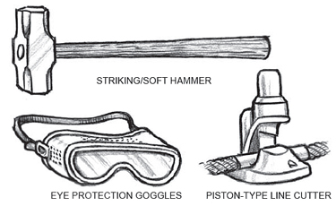
Use caution when cutting lines. Metal chips can be ejected from the line cutter. Make sure guards are in place on the line cutter. Everyone working around a line cutter must wear eye protection. Thrown chips are generally hot, which makes eye injuries more severe. 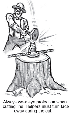
Precautions
Warming fires are common in logging operations, especially during winter months. In wet conditions, loggers have been tempted to use saw gas to get a fire to burn, with disastrous results.
NEVER USE GASOLINE OR SAW GAS NEAR ANY OPEN FLAME
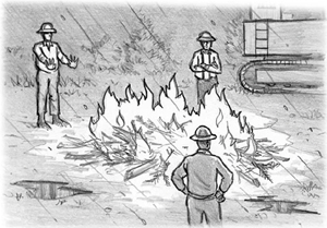 Gasoline quickly vaporizes and becomes explosive. Diesel fuel can be safely used to start a warming fire, but diesel fuel may burn off and fail to ignite wet wood, which has led to considerable controversy in the logging industry over the use of gasoline.
The only authorized use of gasoline to start a fire in the woods involves a mixture of diesel fuel and gasoline in a ratio of 3:1 or 4:1 diesel to gasoline. This mixture is used by the U.S. Bureau of Land Management and U.S. Forest Service for woodland firefighters, using a specially designed drip torch. If this mixture is used at a logging site, the fuel must be stored and dispensed in a labeled can. The only safe way to use the fuel mixture on a fire that is already going is through an authorized drip torch, which dispenses the fuel in a regulated flow and prevents a flame from traveling up the fuel stream into the container. Even with a drip torch, caution is necessary to avoid splashing fuel and setting yourself on fire.
Loggers in a remote location may not have access to diesel fuel and may be tempted to use saw gas alone to start a fire. Don’t do it. Instead, alternative noncombustible products are available to start fires, such as fire starters comprised of sawdust and wax. These products are small and lightweight. Or use pitchy wood from old-growth stumps. Prepare for a warming fire in advance by obtaining a safe fire starter.
Employers must train employees on safe procedures for starting and stoking fires, and emphasize the extreme hazard of using gasoline on a fire. Most people know the danger of using gasoline around a fire, but cases of fatalities and severe injuries from gasoline near fires continue to occur.
Precautions
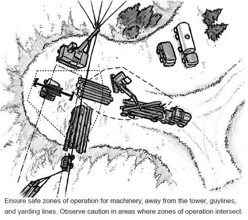
Log loaders use grapple arms or other positive means to handle logs. Clearing and decking logs from the landing chute and loading log trucks makes the loader the most mobile machinery on the landing. Good communication with ground personnel is essential. Machines must be equipped with an audible signal device to alert ground personnel of equipment travel.
Ground personnel must make sure the loader operator knows their location and employ signals and receive acknowledgement whenever entering the loader’s work area. Ground personnel must also pay close attention to hazard areas:
General procedures for safe loader operation also apply to the processor working on the landing. Both machines operate close together in the same conditions. Usually, the processor works the logs directly from the landing chute and hands them off to the loader, which decks them nearby. The loader may then move the logs to another deck, ready to load.
Machines must be in a safe position ready to process and deck the logs at once to keep the landing clear. Always operate on stable and level ground. Use caution when lifting heavy loads, which can tip a machine.
Whenever possible, position the loader and processor so the operators have a full, unobstructed view of landing operations. Avoid placing the loader too close to yarding lines and guylines where the swinging boom could strike a line and cause damage to the equipment and endanger workers on the ground. Also, avoid locating the loader between the yarder and the incoming turn where the operator is exposed to moving logs and swinging chokers. If machines must be located in a hazard area near the turn, the operator must move away while turns are landed and the chokers are pulled free (unless the operator needs to be present to assist with landing the turn).
Machine operators must watch the approaching turn for any unexpected log movement. Try to swing equipment so the entrance side of the cab is not exposed to the turn. Close the entrance doors.
Machine operators must observe the following precautions during operation.
Ensure ground personnel are clear. Machine operators must ensure ground personnel are clear before moving. Logs must not pass over workers on the ground or in occupied vehicles. Beware of blind spots. Coordinate activities with the chaser or other workers before swinging into a blind spot.
Ensure a safe operating zone. Make sure the operation of the boom and swinging logs does not interfere with yarding lines, guylines, or other machines. Any time a log or grapple could swing into the yarder cab, stop and reposition the machine. If possible, remove any standing trees left in the operating circle of the processor or loader.
Maintain Machine Clearance
The rotating superstructure of any machine must maintain at least 3 feet of clearance in all directions. Landings are very active work areas and adequate clearance can be lost without realizing it. The loader operator and ground personnel who can alert the loader operator must regularly check that 3 feet of clearance is maintained. Lives can depend on it. If clearance cannot be maintained, control access to the pinch point with barriers, cones, rope, or other warning devices.
Secure loose logs. When there is danger of a larger log slipping out of the grapples, a strap of sufficient size and length must be used to hold the log. Securely attach the holding strap according to the manufacturer’s recommendations. Use caution when small logs may slip out of the grapples.
Deck logs safely. Place and remove logs in decks in an orderly manner to minimize rolling or shifting. Set logs down gently to avoid flying debris. Stay alert to decking areas as logs are added or removed. A support, such as a rock, stump, or tree, could give way. Rearrange decked logs or move the decks if weather conditions produce stability hazards. Always make sure logs will not slide or roll in the direction of work areas on or below the landing.
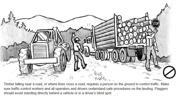
Vehicles must stop and signal before approaching a landing or other work areas, and wait for permission to go ahead. Log trucks entering the landing produce new hazards. Make sure log truck drivers are made aware of safe landing procedures, including the following: Timber falling near a road, or where lines cross a road, requires a person on the ground to control traffic. Make sure traffic-control workers and all operators and drivers understand safe procedures on the landing. Flaggers should avoid standing directly behind a vehicle or in a driver’s blind spot.
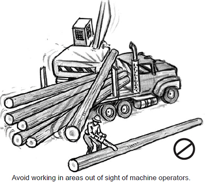 Unloading the Trailer
 Make sure the loader is in a good position to lift the trailer from the truck without overbalancing. Inspect the lifting strap to be sure it is in good condition and strong enough. Also, check that the tiedown used during transport is removed from the trailer. Failure to remove the tiedown can cause the trailer to react violently when lifted. Ensure the lifting strap is held securely by the grapples before lifting the trailer. If necessary, use a spotter (or spotters) to monitor the lift. Handling trailers must be done smoothly and steadily to protect workers on the ground standing by to help attach the reach of the trailer to the hitch. If the trailer is not properly balanced, lower it to the ground and reset the grapple. Before lowering, make sure all workers are well in the clear.
Chaser Safety in Loading Operations
A chaser or other landing worker helping in loading operations faces a variety of hazards. The worker can be struck by a log or chunk that falls off a deck or off the truck, or by moving machines or a swinging log. Work on top of the load can result in a dangerous fall. When working near a loading operation, observe the following general precautions:
- Never pass alongside a log truck being loaded, unless the loader operator gives clear permission to do so.
- Always check log decks, moving logs, and the loaded truck for unstable logs and materials that could be thrown.
- Stay clear of log decks where a loader is working. Do not work behind a log deck out of sight of machine operators. Make an effort to stay visible.
Unloading the Trailer
- Make sure trailer tires are on the ground and the trailer reach is close to the ground before approaching. Never stand under a raised trailer or reach.
- Beware of unexpected movement; the trailer air brakes can bleed off, allowing the trailer to roll.
- Keep hands away from the end of the reach and legs and feet away from under the reach.
- Only grab the trailer from approved hand holds. Do not place a hand on the compensator, which could move and crush the hand.
Loading the Truck
- Never enter the area between the loader and truck until loading is completed and the boom is swung clear or resting on the ground, and the loader operator confirms it is OK to approach.
- Notify the loader operator and truck driver before approaching the trailer to pull the compensating pin, remove bunk locks, or install wrappers. Only remove the compensator lock when the trailer is properly secured by the loader.
- If a wrapper fouls on top of the load, use extreme caution when jerking it free. Pulling a log down off a load is a common source of injury.
- When climbing on the truck or trailer to set stake extensions or secure the load, use caution to avoid slipping on metal surfaces with caulk boots.
- Trim, buck, brand, and paint logs before loading.
- If it is necessary to go on top of the loaded truck to limb or brand logs, make sure all logs are secured by bunks and properly cradled logs, or by wrappers tying all the logs down. Ensure secure footing when reaching overhead and when walking on top of the load. Never stand behind the cab guard during loading.
Loading a log truck requires knowledge of numerous details about the stability of the truck and loaded logs. Loads must be built up so they are stable without the use of wrappers and will not exert excessive strain on wrappers, binders, bunk stakes, or straps.
First, make sure the loader and log truck are positioned so logs will not be swung toward the yarder. If logs are decked nearby, move the truck to a clear area to avoid hazards for workers on the ground.
The loader operator and truck driver must use a positive means of communication to control the movement of the truck during the loading process. Citizens’ band (CB) radios may be used. The truck driver is safest outside the cab in front of the truck during loading, but if necessary, may be in the cab, ahead of the cab guard.
Sometimes drivers will need to raise their stake extensions on the truck and trailer. Try to plan ahead and do this before the driver has to climb on top of load.
The compensating pin or latch should be pulled before the load is completed – best done when the load is about halfway up the stakes. This ensures there is adequate weight to stop the logs from sliding on the bunks if the vehicle has to be moved during loading. The compensating pin or latch can be removed before loading starts if the truck does not have to be moved.
Beware of Falling Logs
If a wrapper fouls on top of the load, use extreme caution when jerking it free. Pulling a log down off a load is a common source of injury.
Each log truck must carry at least five binders and five wrappers, chains, cables, and fasteners in good condition. Before installing wrappers, all logs must be saddled within the stakes or secured by the log loader. Make sure the load is stable before wrappers are installed. All top logs need to be secured by at least two wrappers, evenly spaced near the ends of the logs.
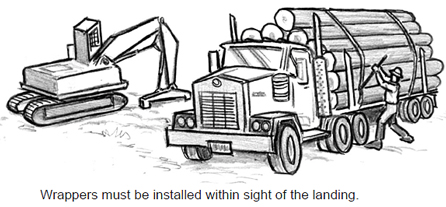
Misthrown wrappers may need to be pulled back off of the top of a load and be rethrown. When pulling off wrappers, beware of unstable logs that could be pulled down. If a wrapper fouls on top of the load, use extreme caution when jerking it free. Pulling a log down off a load is a common source of injury.
When logs are loaded at different locations or decks, log trucks must not be moved unless ground personnel are in the clear or the centers of all logs are below the top of the stakes. A fully loaded truck must not be moved more than 1½ truck-trailer lengths from the loading area unless the load is secured with at least two wrappers or the centers of all logs are below the top of the stakes. All wrappers required to transport the load must be placed on all log loads within sight of the loading area, in case immediate emergency assistance is necessary. It is possible to wrap up away from the landing if there is another person there to watch over the driver and the spot is near enough so the loader operator can offer immediate assistance with his machine.
Quick response can save a life
All wrappers must be thrown within sight of the landing to allow immediate assistance in case a driver pulls a log down on himself.
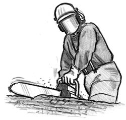
An effective safety and health program in any organization must demonstrate commitment from the top. A logging company owner or manager sets an example for everyone by taking safety seriously. The first step involves establishing a written safety and health program that covers management commitment, supervisory responsibilities, accident investigations, injury reports, employee involvement, hazard identification, training, and annual evaluation of the program. In addition, safety planning and hazard assessment must be completed before beginning work on a unit.
This chapter summarizes the primary issues in a safety and health program, and in general safety planning and hazard assessment. The safety information provided here follows Oregon’s Division 7 Forest Activities administrative rules, sections B, C, D. Refer to the original document for complete coverage of the topics (www.cbs.state.or.us/osha/standards/div_7.html).
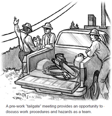 Every logging employer must implement a written safety and health program with the following features.
Written statement of management commitment to safety. Commitment must include provisions for necessary personnel and resources to carry out the safety and health program; monthly inspection of worksites, equipment, work methods, and practices (as the type of operation or character of the equipment requires); and methods to correct hazards.
Supervision. Identify safety and health personnel and resources. Authorize a competent person or persons to supervise all workers and enforce safe work practices. Establish a disciplinary policy that includes additional instruction or retraining. Closely supervise new workers to assure they have received adequate training and they are working safely. Periodically review the safety performance of each worker.
Managing Safety
The company owner or manager, and the siderod supervising the planning and yarding activities at the landing site, are responsible for the safety of the crew. Observe the following points.
Plan operations carefully. Good planning can help control hazards.
Know logging safety rules. Know and enforce Oregon OSHA safety rules and company safety policy.
Pass on knowledge. Top management should pass on knowledge to others and encourage a work environment where co-workers share knowledge.
Provide a safety and health program. Implement the company safety program in the forest operation, including annual fire training. Remember to follow through to investigate, record, and discuss with workers all injuries and near misses.
Plan for emergencies. Along with first-aid training and supplies and communication resources, make sure directions to the worksite and the location in township, range, and section are written down for workers to use in an emergency.
Make sure new workers are adequately trained. New workers eager to do a job well must also demonstrate they can to do it safely. Supervise closely and provide follow-up training. Remind new workers to stay alert to their environment and signals from co-workers.
Accident investigation. Investigate every recordable injury, illness, or fatality to determine the causes involving work conditions and practices as well as individual behavior. Keep a written record of the investigation and results. Identify and implement measures to prevent a similar incident, and inform all workers of the new measures. Also, track and discuss “near misses” with workers and take steps to prevent similar occurrences.
Employee involvement. Encourage all workers to participate in site planning and pre-work safety meetings to discuss site conditions and known hazards. Require workers to report safety and health hazards. Conduct monthly safety meetings with all workers, and keep written minutes and attendance records that are available to all workers.
Hazard identification and control. Identify qualified workers to correct or eliminate hazards identified in pre-work inspections or safety meetings, or reported at other times by workers. Conduct a monthly safety inspection of all worksites, vehicles, machines, equipment, and work practices.
Training. Before starting any work or assigning new work tasks, tools, or equipment, provide job safety and health training to workers, including supervisors, that is adequate for the work task. Training should include a step-by-step discussion of the job, and instruction on how to identify and control hazards; plus, the safe use and maintenance of tools, equipment, machines, and vehicles, including the manufacturers’ instructions. A worker does not need to be retrained if prior training is adequate. Assure that a qualified person presents the training and that the training is conducted in a language and manner that the worker will understand. Keep a written record of training for each worker.
Program evaluation. Review the safety and health program annually. Identify and revise program deficiencies. Keep a written record of the evaluation.
The following safety planning and procedures must be completed prior to any forest work activities.
Pre-work hazard assessment and control. Each day, a competent person must make a general inspection of work areas to evaluate any hazards, including danger trees, snags, logs, rootwads, rocks, and other objects. Any objects likely to move during work activities must be removed, stabilized, or the work arranged to minimize exposure. Consideration must be given to rain, snow, or other weather conditions that could increase the likelihood for objects to move. The competent person must also assess adverse weather conditions, such as heavy rain, high winds, or darkness to determine if work activities can be safely conducted.
Pre-work safety meeting. Hold a pre-work safety meeting with workers to discuss site conditions and known hazards. Ensure that all workers understand emergency evacuation procedures (discussed below). Document the pre-work safety meetings.
Hazard identification. Mark identified hazards that cannot be eliminated with bright-orange hazard identification ribbon. Notify workers of marked hazards in their work areas. Hazard identification ribbon must be available to workers and carried by all cutters. Do not use hazard identification ribbon for any other purpose than identifying hazards and remove the ribbon when a hazard is removed.
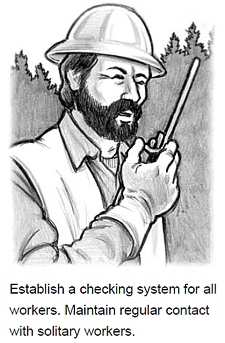 Checking system. Implement a checking system to account for all employees at the end of each work shift. Inform all workers of the checking system. Also, identify a specific person to check on the well-being of lone workers at specified time intervals. Take into account the nature of the work and possible hazards. A check twice a day could be enough, but more frequently could be necessary to assure the worker’s safety. Definitely check everyone in at the end of the day.
Working alone. Require a worker to demonstrate the ability to safely perform a work task before permitting independent work activity. Although certain jobs by their nature may be single-worker assignments, regular contact must be maintained. In certain hazardous tasks, such as fire suppression, operating a chainsaw, loading, moving heavy parts, or any work at a height, two workers must work together as a team in sight or sound of one another.
Medical services. Plan for emergency medical services for the worksite, including specific provisions for lone workers. All workers must understand what to do in an emergency, and when to call air rescue to avoid delay in getting help. All forest-activity workers must be trained in first aid and CPR. Each worksite must have at least one working two-way radio or phone to reach ambulance service (a communication “dead” area must have a means to relay emergency calls through another site). Near the communication device, information must be kept for the name and number of land and/or air evacuation services, written land directions to the worksite, and location by township- range-section or latitude-longitude as required by the emergency responder. Transportation must be available to reach a medical facility or a point where an ambulance or airlift can be met.
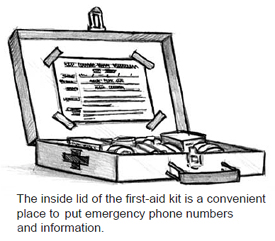 First aid. Each worksite must have a first-aid kit with a supply of required items. In addition, all work vehicles must carry a readily available first-aid kit suitable for the number of workers that use the vehicle and the type of injuries that could occur. Regularly inspect and replenish the first-aid kits, and review the number and content of the kits annually with a healthcare provider. The kits must be clearly marked “First Aid.” All employees must be informed of the location of first-aid supplies.
Power line safeguards. Maintain a clearance of at least 15 feet from overhead power lines for all machines, trees, logs, and cables. Any overhead power line must be considered to be energized until the line owner or utility authority indicates otherwise. In difficult operating conditions, designate a spotter to observe clearance and provide timely warning. The power company must be notified for any situation where work needs to occur within the minimum clearance area. If contact is made with a power line or the supports are damaged, the power company must be notified immediately and all workers must remain clear of the area until advised that conditions are safe.
Field sanitation. Employers should consider providing toilet and hand-washing facilities or sanitary kits, when feasible. Providing potable drinking water is also important for worker health. Field sanitation is not required for logging, but sanitation needs to be assessed if watchmen are living on site.
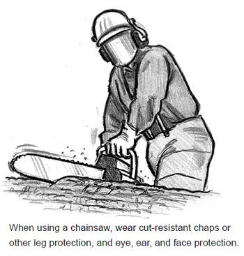 The type and condition of clothing and personal protective equipment is important to prevent injury. Personal protective equipment must be maintained in serviceable and effective condition or removed from use. Inspect personal equipment prior to each work shift, and repair defects or replace the equipment.
The employer must provide workers with the necessary personal protective equipment as demanded by the job they are performing (except clothing and boots), and require that the equipment is used appropriately when necessary and remains in serviceable condition.
Clothing must be strong and durable, and adequate to stay warm and dry. Be prepared for weather changes. Discomfort from cold and wet can reduce alertness and the ability to move quickly if an immediate hazard arises.
Wear clothing that fits close, but loose enough to move freely. Trousers should be without cuffs to avoid hang-ups. Suspenders are useful to allow a reasonably loose waistband, and hold trousers in a comfortable position even when wet.
All yarding and loading workers, unless covered by a cab or canopy, must wear a hardhat that complies with the American National Standards (ANSI) Z89.1 1986, Z89.1 1997, and Z89.1 2003. A stamp inside the hardhat should show it has met one of the above standards. Hardhats must be highly visible, in contrast to the background – typically orange – to enable machine operators to readily see them.
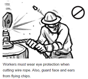 Eye and Face Protection
 Wear eye and face protection whenever wood chips, sawdust, or flying particles present a hazard. Workers who cut wire rope must wear eye protection. Chainsaw operators may use logger-type mesh screen.
Workers must wear hearing protection when operating a chainsaw or other noise-producing equipment, or working on the landing (unless the 8-hour average noise level is less then 85 dB). Both muff-type ear protection and earplugs will not prevent hearing warning signals or speech, and may actually improve hearing by cutting out excessive noise. Workers exposed to noise must have an annual hearing checkup.
Workers must use hand protection, such as cotton gloves or other suitable protection, whenever the work requires handling lines or other rough materials, or when the nature of the work requires hand protection. Also wear hand protection to prevent exposure to harmful substances from skin absorption, or chemical or thermal burns.
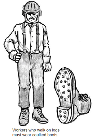 Leg Protection
Chainsaw operators must wear flexible ballistic nylon pads, chaps, or other equivalent protection to protect the legs from the top of the thigh to the top of the boot. Kickback from a chainsaw is a serious hazard. Protect yourself. Designs for currently available leg protectors make them easy to use.
The only exception to this rule is when using a chainsaw while aloft in a tree, supported by climbing spurs and climbing belt, when leg protection is not required.
IMPORTANT: Slips, trips, and falls in logging operations are a principal cause of injury. Make sure boots are appropriate for work conditions and in good repair.
All workers must wear heavy-duty boots that cover and support the ankle and are water repellent in wet conditions. Workers who walk on trees, logs, or boomsticks must wear sharp caulked boots (or the equivalent). In ice, snow, mud, rocky terrain, or other conditions that render caulks ineffective, workers must wear heavy-duty nonslip boots. Workers who operate chainsaws must wear cut-resistant foot protection.
Smaller tools and equipment also require safe handling. Observe the following rules and tips to avoid injury.
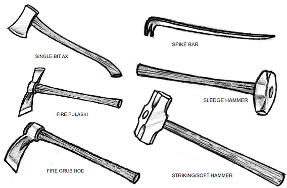
Observe the following precautions when spiking guylines or driving spikes into any hard wood.
The following overview of fire prevention and suppression requirements summarizes Division 7 standards and a description of laws and rules provided by the Oregon Department of Forestry. Consult original sources for complete coverage. For more information, contact any office of the Oregon Department of Forestry, Coos Forest Protective Association, Douglas Forest Protective Association, or the Walker Range Fire Patrol Association.
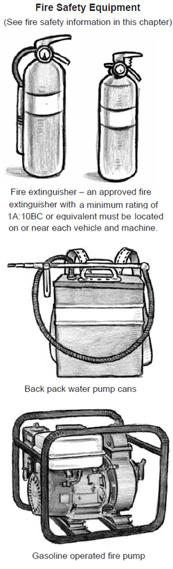 Permits. Using fire or power-driven machinery normally requires an annual permit from the district before starting an operation. District closedowns may regulate activity during fire season.
Action to control fires. The landowner and operator must immediately proceed to control and extinguish any fire started during operation activity, any fire that results from operation activity, and any fire that results from burning. The physical capacity of each employee assigned to control a wildland fire must be taken into account before and during the assigned tasks. Workers must be in teams of two or more and close enough to give assistance to one another.
Training. All workers who may be called upon to do wildland fire suppression or prescribed fire activities must receive annual Basic Wildland Fire Safety Training.
Cable logging. Clear flammable debris from the area below blocks for at least 10 feet in all directions. Also, equip each block with a pump-equipped can or bladder with at least five gallons of water and a shovel. Do not permit moving lines to rub on rock or woody material in such a way that sparks or heat could ignite a fire.
Snags. The district may require certain designated snags to be felled before or during an operation if they constitute a hazard.
Machines. Most engines must be equipped with a spark arrester. Prevent debris from accumulating nearby. An approved fire extinguisher must be readily available.
Watchman. After machinery is shut down, a watchman must conduct a continual visual observation of the operation area for up to three hours with adequate equipment to try to control and extinguish a fire, and summon assistance in an emergency.
Power saws. Each power saw must be equipped with an exhaust system that has not been modified and meets exhaust temperature and other requirements. Follow safe procedures when fueling (See guide on the next page). A fire extinguisher and shovel must be immediately available.
Flammable and combustible liquids. Vehicle engines, except diesel engines, must be shut off while being fueled. Fill gasoline containers on the ground and not in the back of a pickup, which can produce a spark from static electricity. Follow the requirements for safe storage and transport.
Explosives. Only qualified, designated personnel are allowed to handle explosives and blasting agents. Vehicles used to transport explosive materials must be equipped with at least two fire extinguishers and follow the requirements for safe storage and transport.
Fire extinguishers. Most equipment powered by an internal combustion engine must have an approved fire extinguisher available that is fully charged and ready for immediate use. Portable extinguishers must have an annual maintenance check and dated inspection tag.
Water supply and equipment. Most operations require a water supply, including pump, hose, and nozzle ready for immediate use. Equipment must meet specific requirements.
Fire tool box. Firefighting hand tools are required on most operations. Store all required firefighting hand tools in a clearly identified tool box kept ready for immediate use. The number of tools needed depends on how many people work in an operation area. A crew of 10, for example, requires 2 axes or pulaskis, 3 shovels, and 5 hazel hoes/pulaskis.
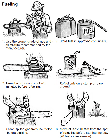
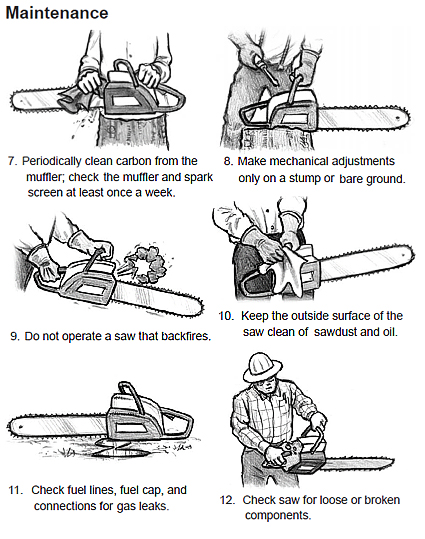
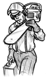 Only use a chainsaw if adequately instructed, trained, or experienced in its use. Injuries from saw kickbacks are usually severe, meaning permanent disability. Train before you cut, wear personal protective equipment, know the saw, and be sure it is in serviceable condition. Furthermore, observe the following tips for safe use:
Safety Precautions
Common Causes of Chainsaw Injuries
- Working in an awkward position, off balance, or with poor footing.
- The chain tip touches branches, an obstruction, or other materials.
- The saw has mechanical problems, such as an improperly filed chain, loose handle bars, clutch drag or improperly adjusted idle speed.
- The saw chain binds in the cut.
- The end of the bar strikes uncut wood in the cut.
- Running a hand across teeth during saw sharpening.
In a remote work location, a logger’s first-aid skills can save a life. Review the following main points to stay fresh on what to do.
Loggers are required to have first-aid supplies and an emergency medical plan for all logging sites. All loggers must have first-aid training.
Getting help to the site quickly requires forethought. An operable phone or two-way radio must be available for external communications to an ambulance service, even in remote locations. Any member of the crew must be able to tell responders how to reach the site. Keep the location in township, range, and section numbers, plus directions, posted near the communication link. Write out the directions so they can be easily read aloud. A person in a panic may have difficulty organizing complete information otherwise. Temporary road signs may be necessary to help responders navigate through forest roads. Someone may also need to meet the emergency crew along the route to reach the site quickly.
Get the right help. If an injured individual needs to be moved, consider the number of people that may be needed to assist and if the number of emergency responders is adequate. Plan procedures for helicopter rescue where rapid evacuation is essential.
Check out the situation first. The first priority could be to remove an injured worker from an impending danger, and avoid danger to yourself. Rescuers are sometimes overcome by the same harm as the one they try to rescue. Stay calm and alert when rushing to help an injured co-worker. If it is not necessary to move the worker, keep them in place, warm and comfortable, and protected from adverse weather. Initiate the emergency medical plan immediately.
The main threats to life are:
Check breathing. Check to make sure the mouth and throat are clear of any obstruction. Use a finger to clear any vomit, blood, lower dentures, or other objects as necessary. Use mouth-to-mouth resuscitation techniques if breathing has stopped.
Stop bleeding. Immediately put pressure on any bleeding wound, and apply a dressing and bandage as soon as possible. Raise the bleeding part to slow bleeding. Have the person sit or lie down.
Care for an unconscious person. An injured person that loses consciousness risks choking. Put an unconscious person on their side, injured side down, with their cheek on the ground. Check to be sure breathing is clear. Support the person so they do not roll onto their back.
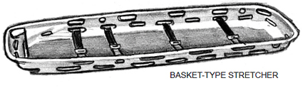
Various signs and signals are useful during logging activity to safely coordinate activity. Many are required. This chapter summarizes regulations for signs and signals and lists standard signals.
All workers need to understand the signals used in a logging operation. A list of standard yarding whistles and control systems for equipment, plus any additional signals used onsite, must be available to workers at the worksite. All required signals listed in Oregon OSHA Division 7 Forest Activities are included here. Refer to the regulations for full coverage of work requirements.
Audible signals such as whistles, horns, or radios must be used whenever noise, distance, restricted visibility, or other factors prevent clear understanding of natural unassisted voice communications. Hand signals may be used within 300 feet and plain view of machine operators. General requirements for using signals include the following points:
Voice transmission by radio is an acceptable method to signal operations as long as whistle signals are sounded before any lines are moved. Permits are required for tone frequencies in each area. Citizen band (CB) radios cannot be used to activate any signal, machine, or process. Two or more whistle signal receivers on the same tone frequency is prohibited.
Test radio systems each day before work begins. Find and correct the source of failure or problems such as interference or fadeout before use.
In the operational setting, make sure electrical signal system wires and attachments are weatherproof. Guard any spare transmitters against accidental activation to avoid confusion.
Communication protocol between the rigging crew and yarding engineer includes the following points:
The following standard yarding system whistle signals are required in operations. Note that different sets of signals apply to different yarding systems.
*Dash (-) indicates longer spacing between signals.
| HIGH LEAD WHISTLE SIGNALS | |
|---|---|
| 1 short | Stop all lines |
| 3 short - 3 short | Ahead easy on mainline |
| 3 short | Ahead on mainline |
| 2 short | Ahead on haulback |
| 2 short - 2 short | Ahead easy on haulback |
| 3 short - 1 short | Ahead on haywire |
| 3 short - 1 short - 3 short | Ahead easy on haywire |
| 4 short or more | Slack mainline |
| 2 short - 1 short | Slack haulback |
| 3 short - 1 short - 4 short | Slack haywire |
| 3 short - 2 short | Standing tight line |
| 2 short | Tightline while lines are running, or break tightline if lines are running tight |
| 3 short | When rigging is in: haywire back on haulback |
| 3 short - plus "X" number of shorts | When rigging is in: indicates number of sections of haywire back on rigging |
| 3 short - 2 short | When rigging is in: haywire back on rigging |
| 1 short | When rigging is in: chaser inspect and repair rigging |
| 2 short | When rigging is in: no chokers back |
| 2 short - 1 short - plus "X" number of shorts | When rigging is in: number of chokers back |
| 2 short - 1 short | When rigging is in: slack haulback, hold all lines until 2 short blown |
| 3 medium | Hooker |
| 3 medium - 4 short | Hooker and the crew |
| 5 long | Climber |
| 4 long | Foreman |
| 1 long - 1 short | Start or stop work |
| 7 long - 2 short | Person injured, call transportation and stretcher |
| 1 long- 1 short | Fire |
| 3 short - 1 short | Acknowledge by engineer to signify a hazardous turn |
| GRABINSKI SYSTEM | |
| 2 short - 1 long | Slack mainline and haulback together |
| 2 long | Take off or put on rider block |
| SLACKLINE WHISTLE SIGNALS | |
| 2 short - 2 short - 2 short - 1 short | First cable up when road has been changed and tailhold made fast |
| 2 short - 2 short- 2 short | Drop skyline |
| 1 short | Stop any moving line |
| 1 long | When logging, slack skyline |
| 2 short | Ahead on skyline |
| 1 long - 2 short | Ahead easy on skyline |
| 3 short | Ahead on skidding line |
| 3 short - 3 short | Ahead easy on skidding line with slack haulback |
| 4 short | Slack skidding line |
| 2 short - 2 short - 2 short - 2 short | Ahead easy on haulback with slack skidding line |
| 2 short - 2 short | Ahead on haulback |
| 2 short - 1 short | Slack haulback |
| 2 short - 3 short | Pick up skyline and skid |
| 2 short - 2 short - 2 short | Pick up skyline and skin |
| 3 short | When carriage in: haywire back on haulback |
| 3 short - 1 short | When haywire out: ahead on haywire |
| 3 short - 2 short | Tightline |
| 3 short - 1 short - 4 short | Slack haywire |
| 3 short - 1 short - 3 short | Ahead easy on haywire |
| 2 long | Ahead on transfer |
| 2 long - 4 short | Slack transfer |
| 2 long - 2 short - 2 short | When carriage is in: transfer back on carriage |
| 3 short - plus "X" number of short | When carriage is in: number section back on carriage |
| 2 short - plus "X" number of short | When carriage is in: number of chokers |
| 1 short | When carriage is in: inspect rigging, repair and send back |
| 2 short - 1 short | When carriage is in: slack haulback and hold all lines until 2 short are blown- then send back |
| 3 short - 3 short | When carriage is in: send black powder |
| 5 medium | Tail rigger |
| 5 medium - 4 short | tail rigger and that crew |
| 3 medium | Head hooker |
| 3 medium - 4 short | Second hooker and that crew |
| 5 long | Climber |
| 4 long | Foreman |
| 1 long - 1 short | Start or stop work |
| 7 long - 2 short | Person injured, call transportation and stretcher |
| 1 long - 1 short repeated | Fire |
| RUNNING SKYLINE WHISTLE SIGNALS | |
| 1 short | Stop all moving lines |
| 2 short | Skin carriage back |
| 2 short - 1 short | Slack haulback |
| 2 short - 2 short | Skin carriage easy |
| 2 short - 3 short | Standing tightline |
| 1 short - 2 short | Ahead on dropline |
| 4 short | Slack dropline |
| 1 short - 4 short | Slack both mainlines |
| 1 short - 1 short | Stop dropline going up and move carriage forward |
| 3 short | Move carriage forward |
| 3 short - 2 short - 3 short | Move carriage forward easy |
| 3 short - 1 short | When haywire is out: ahead on haywire |
| 3 short - 1 short - 4 short | Slack haywire |
| 3 short | When carriage is in: haywire |
| 3 short - plus "X" number of short | When carriage is in: number of sections |
| 3 short - 1 short - 2 short | When carriage is in: haywire back on carriage |
| 2 short - plus "X" number of short | When carriage is in: number of chokers |
| 4 short | When carriage is in: inspect rigging, repair, and send back |
| 1 short | When carriage is in: hold all lines until 2 shorts, then send back |
| 3 medium | Hooker |
| 3 medium - 4 short | Hooker and crew |
| 5 long | Climber |
| 4 long | Foreman |
| 1 long - 1 short | Start or stop work |
| 7 long - 2 short | Person injured, call transportation and stretcher |
| 1 long - 1 short repeated | Fire |
| 3 short - 1 long | Acknowledged by engineer to signify hazardous turn |
| TENSION SYSTEM WHISTLE SIGNALS | |
| 4 short | Release tension |
| 1 short | Stop carriage and start unspooling tong line |
| 1 short | Stop tong line |
| 1 short | Resume unspooling tong line |
| 1 short | Will stop any moving line or slack tong line when carriage is stopped |
| 2 short - 2 short | Go into interlock and go back |
| 2 short - 4 short | Slack haulback and let carriage down |
| After turn is set - 2 short | Go ahead on tong line |
| 2 short - 3 short | Go ahead easy on tong line |
| 3 short | Go into interlock and take carriage to landing |
| 3 short - 3 short | Ahead easy on carriage |
| 1 short - 2 short | Increase tension on tong line when carriage is going in |
| 1 short - 1 short | Decrease tension on tong line when carriage is going in |
| 3 medium | Hooker |
| 3 medium - 4 short | Hooker and crew |
| 5 long | Climber |
| 4 long | Foreman |
| 1 long - 1 short | Start or stop work |
| 7 long - 2 short | Person injured, call transportation and stretcher |
| 1 long - 1 short repeated | Fire |
| SKIDDER WHISTLE SIGNALS | |
| 1 short | Stops moving carriage - stops or goes ahead on slack- puller (as case may be) |
| 2 short | Go ahead on skidding line holding carriage |
| 1 short - 2 short | Pick up skidding line, easy |
| 2 short - 1 short | Shake up carriage to clear choker |
| 2 short - 2 short | Ahead on receding line |
| 3 short | Ahead on carriage, holding at present level, using interlock |
| 3 short - 3 short | Ahead easy on skidding line |
| 2 short - 2 short - 2 short | Slack skyline, cable down |
| 2 short - 2 short - 2 short - 1 short | Pick up skyline, cable up |
| 2 short - 2 short - 4 short | Slack receding line |
| 2 short - 4 short | Slack skidding line |
| 2 short - 2 short - 1 short | Tighten all lines |
| 1 short - 4 short | Slack off slack puller |
| 1 short - 2 short | Pick up slack puller when slack |
| 2 short - 2 short - plus "X" number of short | When carriage is in: number of chokers wanted |
| 2 short - 2 short - 1 long | Bull choker |
| 1 short | When carriage is in: Inspect buttrigging |
| 2 short - 4 short - 1 short | For each additional 10 feet of tong line |
| 1 long - plus "X" number of short | Number of coils of haywire wanted |
| 5 medium | Tail or second rigger |
| 5 medium - 4 short | Tail or second rigger and that crew |
| 2 medium | Skidder head rigger |
| 3 medium | Hooker |
| 3 medium - 4 short | Hooker and that crew |
| 2 long | Ahead on transfer |
| 2 long - 4 short | Slack transfer |
| 1 short - 3 short | Ahead on carriage with slack puller line |
| 1 long | Ahead on haywire |
| 1 long - 4 short | Slack haywire |
| 1 long - 3 short | Ahead easy on haywire |
| 5 long | Climber |
| 4 long | Foreman |
| 1 long - 1 short | Start or stop work |
| 7 long - 2 short | Person injured, call transportation and stretcher |
| 1 long - 1 short repeated | Fire |
Warning signs must be prominently displayed a minimum of 300 feet in advance of forest activities that create hazardous conditions for road traffic. A flagger must also be used. Warning signs and flagging activities along state and county roads must comply with uniform traffic control requirements.
If the road is closed to through traffic, warning signs and barricades are sufficient. Remove or cover signs when operations are done or interrupted. In remote locations, regular road signs can be useful to direct traffic and emergency vehicles to the site.
Flaggers may be necessary at a busy landing to control movement of log trucks and machines. Flaggers must wear high-visibility vests and use a “STOP/SLOW” paddle to control traffic. The “STOP/SLOW” paddle must be eight sided, with a minimum height and width of 18 inches, a red background with 6-inch white letters on the “STOP” side, and an orange background with 6-inch black letters on the “SLOW” side.
Warning signs must be diamond-shaped, a minimum 24 inches per side, with an orange background and 4-inch black letters. Stop signs must be eight-sided, with a minimum height and width of 24 inches, with a red background and 6-inch white letters.
Warning signs must be worded to describe the hazard, type of operation, or action to be taken, as in the following examples:
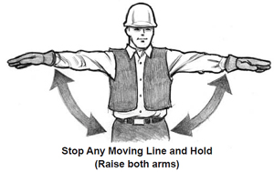 Hand signals may be used within 300 feet of the machine operator as long as the machine operator has a clear view of the person using the hand signals. Signaling by throwing any type of material is prohibited.
The 13 following figures illustrate standard hand signals.
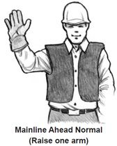
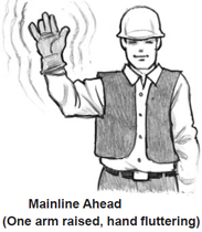
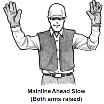
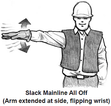
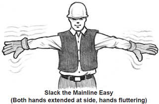
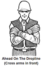
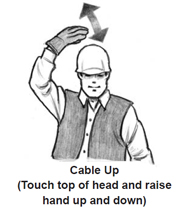
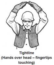
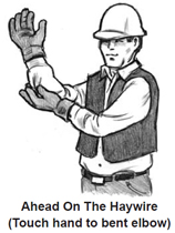
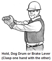
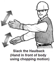
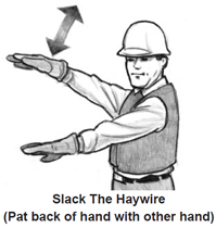
This glossary lists terms related to yarding, loading, and landing operations, with definitions from Federal OSHA, Oregon OSHA Division 7 Forest Activities, and WorkSafe BC, plus additional definitions for terms used in this handbook. Most terms related to falling and firefighting are not included.
A-FRAME: A structure of two independent columns fastened together at the top and separated at the bottom to stabilize the unit from tipping sideways.
ALTERNATIVE COMMUNICATION SYSTEM: A system other than horn or whistle – by voice, hand, or media – that provides a safe and reliable method of communication between crew members.
ANCHOR: Any stump, tree, deadman, earth-anchor, or alternative object used to secure a skyline, guyline, or rigging blocks.
ANCHOR POINT (tree climbing): A secure point capable of providing life support.
APPROVED CONTAINER: A metal or polyethylene (plastic) container for flammable liquids up to 5 gallons, approved by a nationally recognized testing lab.
ARCH: Any device attached to the back of a mobile vehicle, used to raise one end of logs for easier movement.
ASCENDERS (jumars, gibbs): Any climbing device used to ascend a fixed vertical rope. The term ascenders usually refers to mechanical devices.
BABBITT: Method to secure a device to a wire rope end to form a terminal, using an alloy composed of several soft metals.
BACK CORNER: Location where the tailhold on the haulback side turns the haulback around the corner.
BACK END: The farthest point away from a landing or yarder in a setting; usually referred to as the tailblocks.
BACK GUY: The guyline opposite lead of the mainline; takes most of the pull.
BACK LINE: That part of the haulback between the yarder and the corner block.
BALLISTIC NYLON: A high-tensile nylon fabric designed to provide protection from lacerations.
BALLOON: When a turn of logs is raised in the air unintentionally. A method for changing logging roads.
BASE OF TREE: That portion of a tree that is not more than 12 inches above highest ground level.
BELAY (snubbing): A method of protecting a climber in case of fall, using a safety rope held by a person on the ground, secondary to the main climbing rope.
BELL: The component that slides on a choker; when a worker chokes a log, the bell secures the knob.
BELLY: A sag in any line.
BENDABILITY (wire rope): The ability of wire rope to bend through a sheave or block and come back to original shape without causing damage to the line.
BIGHT OF THE LINE: A hazard zone created by one or more lines under tension, or a point on a line where a rigging chain is attached. An unintentional bend or deviation in a line caused by tree stumps or other obstacles preventing the line from running straight.
BINDER: A hinged lever assembly for connecting the ends of a wrapper to tighten the load restraining devices (log trucks, flatbeds, lowboys, etc.).
BIRD-CAGING: Twisting of wire rope so strands become separated and form a cage-like effect.
BLOCK: Used to change direction of a line, composed of a metal case enclosing one or more sheaves and equipped with a hook, swivel, or gooseneck for rigging attachment.
BLOW-DOWN: Trees that have been blown down as a result of wind.
BOLE (tree stem, tree trunk): The main stem of a tree of substantial diameter.
BOOM: The articulated lifting arm on backhoes, excavators, log loaders, and similar machinery. Also the arm or jib that extends from the spar on cranes.
BOOMS TICKS: Long log with chain holes drilled in both ends to contain encircle and contain loose logs in a log pond or river.
BRANDING: Striking the end of a log with a hammer embossed with a brand to identify ownership of logs.
BREAKING STRENGTH: The point of failure for a wire rope or chain under load.
BRIDLE: A method to secure a guyline to two stumps with a block and strap.
BRIDLE HITCH: A method of choking a log from opposite sides by using two chokers.
BROW LOG: A log placed parallel to any roadway at a landing or dump to protect carriers while loading or unloading.
BUCK: To cut a fallen tree into logs.
BUCKLE: To bend under strain.
BUNK: Framework designed to contain logs.
BURL: A half-spherical growth on a tree with deformed grain.
BUTT: Bottom of a felled part of a tree.
BUTT LOG: Portion of a felled tree from the butt to the first bucking cut.
BUTT WELDING: The practice of welding something end to end.
BUTTRIGGING: Swivel system to connect the mainline to the haulback and attach chokers.
CABLE YARDING: The movement of trees or logs from the area where they have been fallen to a landing by attaching them to a cable system that is supported by a metal tower (wood spar) and/or intermediate support or tailtrees.
CAULKS (calks, chalks): Heavy leather boots containing numerous steel caulks or spikes. A part of the fallers safety equipment used to promote secure footing.
CANKER: Fungal decay in a tree that can reduce the holding strength of branches or trunk.
CARABINER: An oblong metal ring with a spring-loaded gate on one side, used for various purposes in climbing, such as attaching equipment to the climber or securing the climber to a rappel system.
CARRIAGE: A wheeled device that rides on a skyline, used for hauling logs.
CAT’S PAW: A simple nonslipping knot used on fiber or wire rope with the line running through an eye and looped back on itself to make a quick connection.
CHASER: A worker who unhooks chokers at the landing; also called the “landing worker.”
CHEST HARNESS: Straps placed around the chest and shoulders to secure a chest attachment point.
CHOCK: A block, often wedge-shaped, used to prevent movement, such as a log from rolling or a wheel from turning.
CHOKE: To pass a line or choker around a log or other object and pull it tight.
CHOKER: Length of wire rope, chain, or synthetic material with attachments for encircling a log to be yarded.
CHOKERSETTER: A member of the rigging crew who sets chokers under the direction of a rigging slinger.
CHORD: A straight line that links two points on a circle or curve, used in calculating deflection and payload capacity.
CHUNK OUT: To remove log chunks, branches, and debris from a landing or work area.
CLIMBER: A person qualified to climb a tree; the person climbing.
CLIMBING BELT (lineman-type belt, body belt, safety belt): A wide-padded belt with two large metal D-ring attachment points on the sides. A climbing belt does not have an attached chest harness or attached leg straps.
CLIMBING HARNESS : A type of harness that provides both pelvic and upper body support and can be adjusted to fit individual climbers. Climbing harnesses may be a one-piece full-body harness or a two-piece design that meets industry recognized standards.
CLIMBING HELMET: A specialized helmet with a three-point chinstrap to stay in place during a fall and rating to protect against side and top impacts.
CLIMBING LINE: A rated rope used in tree climbing for ascending into a tree, descending from a tree, and/or working aloft in a tree, with a 5,400-pound minimum breaking strength.
CLIMBING SPURS : L-shaped metal shanks that attach to the foot and lower leg, used to ascend or descend a tree bole by means of a sharp spike (gaff) that penetrates the tree bark and sticks into the wood of the tree.
CLINOMETER: A handheld optical instrument used to measure angles of a slope.
COMPETENT PERSON: A qualified person authorized by the employer to identify existing and predictable hazards in the surroundings and work conditions and to eliminate the hazards or take corrective actions.
CORD: A measure of wood quantity; typically a stack measuring 4 ft. x 4 ft. x 8 ft.
CORNER BLOCK: The first block the haulback passes through on its way to the tailblock.
CORRIDOR: A cleared strip for a skyline or guyline.
COUNTERWEIGHT: Extra weight added to the back of mobile machines to increase lifting capacity.
CRIBBING: A log lattice used to support and usually level the end of a bridge, road, or the base for equipment.
CROSSING THE LEAD: Intentional or unintentional falling of a tree across the established lead of falling direction. Although crossing the lead may be caused by wind, it generally is a result of improper falling technique.
CROTCH LINE: Two short lines attached to the same ring or shackle, used for loading or unloading.
CRUMMY: Vehicle used to transport fallers to and from the falling and bucking area.
CULL: A tree or log which is considered unmerchantable because of defects.
CUT-UP-TREE: A tree left standing, with falling cuts started or completed.
CUTTER: See Faller.
DANGER TREE: A standing tree, alive or dead, that presents a hazard to workers, due to deterioration or physical damage, and the direction of lean.
DBH: Diameter at breast height.
DEAD MAN: Buried log or other object used as an anchor.
DEBARK: To remove bark from trees or logs.
DECK: A stack of trees or logs.
DEFLECTION: The amount of sag in a line measured at midspan, expressed as a percentage of the horizontal length of the span.
DESCENDERS: Any rappelling device used to descend a vertically fixed rope. Designated ignated person: An individual assigned by the employer to perform a specific duty or duties.
DIRECT SUPERVISION: Supervision by a competent person who watches over and directs the work of others who are within sight and unassisted natural voice contact.
DOG (pawl): Action of blocking any movement. A pawl used as a stop on a ratchet wheel. On a chainsaw, pointed teeth on the saw body that dig into the tree with applied pressure and assist cutting.
DOG LINE: Type of line used to fasten logs or timber products together by the use of dogs.
DOUBLE ENDED LOGS: Two logs end to end on the same lay.
DRESS A KNOT: To orient the rope parts of a knot so they are properly aligned, straightened, or bundled. This is often necessary for proper operation of the knot or to reduce rope stress.
DRIFT CARRIAGE: A carriage that rides on the skyline and is controlled by the mainline, or mainline and haulback.
DRIP TORCH: Special equipment used by firefighters and forest workers to make controlled fires, with an applicator that drips liquid fuel in a mixture of 1 part gasoline to 4 parts diesel (1:4).
DROP LINE: The length of line from the carriage to the hook or end connector that holds the choker.
DRUM: A mechanical device on which line is spooled or unspooled.
DUTCHMAN (yarding): A block arrangement used to change the lateral placement of a line, or pull the bight of a line to assist in landing logs.
DYNAMIC LOAD: A load due to acceleration of force, as in a log going from partial to full suspension.
DYNAPIC ROPE: A rope that has an elongation of 40 to 60 percent at the breaking strength and typically a 2 to 8 percent elongation at a working load of 200 pounds. ELASTIC LIMIT: The point beyond which a stretched line will not return to its original length once tension is released.
ELASTICITY (wire rope): The facility of a wire rope to resume its original shape once tension is released after stretching under load.
EMERGENCY CARE: Care provided by a person who is first aid and CPR trained.
EMERGENCY MEDICAL SERVICE: Care provided by a medically trained person such as in a hospital, clinic, ambulance, or rescue vehicle.
ENDURANCE LIMIT (wire rope): Fifty percent of breaking strength for all lines. Using a line over the endurance limit increases line fatigue.
EQUIPMENT ANCHOR : Machinery used as an anchor.
EQUIPMENT PROTECTION DESIGNATIONS: The listing of specific guarding requirements for specific logging machines.
ESCAPE ROUTE: A planned and understood route to move to a safe area.
EXPERIENCED PERSON: A person with sufficient training, experience, and skill in a given process to be knowledgeable of all aspects of that process to work without direct supervision.
EXTENSION: A line added to another line to increase its length.
EXTREME WEATHER CONDITIONS: Includes, but not limited to: (a) strong winds (timbered areas only): wind velocity that reaches sufficient force to blow limbs from standing trees, cause windfalls, or prevent cutters from falling trees in the desired direction; (b) impaired vision: conditions such as falling snow, sleet, mist, fog, rain, dust, or darkness that substantially impair visibility, so workers cannot clearly see signals, moving vehicles, equipment and lines, falling trees or other hazards; (c) hazardous snow or ice: slippery conditions prevent escape from hazards; or (d) lightning.
EYE: A loop at the end of a wire or fiber rope, spliced or press-fitted.
FACE: Edge of area formed along standing timber as timber is felled. Also directional felling cut placed in front of tree toward direction of fall.
FAIRLEAD: Sheaves, rolls, or a combination, designed to receive a line from any direction and guide it to properly spool onto a drum with minimum burning.
FALL: To cut down trees.
FALL BLOCK: A long, narrow block with a thick shell, a small sheave at one end, and a gooseneck at the other, used in northbend and southbend systems to add mechanical advantage to lift the turn to the skyline.
FALLER: A person who falls (cuts down) trees.
FATIGUE (wire rope): Condition when individual wires in a cable begin to break.
FELLER-BUNCHER: Mobile machinery designed to hold, cut, and pile trees for yarding or skidding.
FERRULE: A metal sleeve or collar, babbitted or pressed to the end of a wire rope to form a knob.
FIRE WATCH: A worker who remains at a logging site up to three hours at the end of each day, or stays overnight at some seasons, to watch for possible fires caused by logging activities.
FOPS (falling object protective structure): Structural members arranged in such a way to reasonably protect operators from falling objects such as trees, rocks, etc.
FOUR-INCH TIE-IN: A self-belay (snubbing) system usually consisting of a rope, webbing, and carabiners. It is used as a safety line to secure the climber to the tree below the 4-inch bole diameter and at 3-foot intervals along the bole when climbing above the 4-inch bole diameter.
FRONT-END LOADER: A mobile machine mounted on a wheeled or tracked chassis, equipped with a grapple, tuck, bucket, or fork-lift device, and employed in the loading, unloading, stacking, or sorting of logs or materials.
GOOSENECK: The yoke of a block.
GROUNDED (cutting): Placement of a tree on the ground.
GROUNDED (electrical): A method to dissipate static or electrical charges.
GROUNDED (machines): The placement of a machine component on the ground or device where it is firmly supported.
GUARDED: Covered, shielded, fenced, enclosed, or otherwise protected by means of suitable enclosures, covers, casings, shields, troughs, railings, screens, mats, or platforms, or by location to prevent injury.
GUTHOOK: To grapple or choke a log in the middle.
GUYLINE: A standing line used to support or stabilize a spar, tailtree, intermediate support tree, machinery, or equipment.
HANG-UP (falling): A tree leaning against another tree or object which prevents it from falling to the ground.
HANG-UP (yarding): Logs stuck behind a stump or other obstacle during yarding. Rigging fouled in some manner.
HAULBACK: A line used to pull the buttrigging and mainline to the logs to be yarded.
HAULBACK BLOCK: Any block the haulback line passes through including the corner block and tailblock.
HAYRACK: A type of loading boom where two tongs are used and logs are suspended. A transporting vehicle with multiple sets of bunks attached to a rigid frame usually used for hauling logs.
HAYWIRE (strawline): Light wire rope used to haul heavy lines or blocks into position.
HEEL BOOM : A type of loading boom where one tong is used and one end of the log is pulled up against the boom.
HIGHLEAD: A system of logging where the mainline is threaded through the mainline block which is located near the top of the spar or metal tower to obtain a lift of the logs being yarded and is returned to the vicinity of the logs by a haulback line.
HIGH-VISIBILITY COLORS: Bright or fluorescent white, lime green, orange, yellow, red, or aqua colors that stand out from the surrounding background color and are easily seen.
HOOKTENDER: The worker that supervises the method of moving the logs from the woods to the landing.
HUNG/LODGED TREE: See Hang-up (falling).
IN THE CLEAR: A position within the work area where the probability of hazardous contact with vehicles, machines, falling trees, moving logs, rootwads, chunks, material, rigging, and equipment is minimized by distance from the hazards and/or use of physical barriers, such as stumps, trees, terrain, or other objects providing protection.
INTERMEDIATE SUPPORT TREE: A tree or tree used to elevate and support skylines.
JACK: A hanger device used to support a skyline.
JACKPOT: An area in which the trees have not been felled in any particular lead or direction, resulting in unstable, crisscrossed logs, usually difficult to break free. Such a situation is typically a result of poor falling technique.
JACKLINE: A line rigged from one or between two intermediate support trees to hold a jack for the skyline.
JACKSTRAWED: Trees or logs piled in an unorderly manner.
JAGGERS : A projecting broken wire in a cable.
JILL-PO KE: A log driven out of a pile to protrude out one end.
KNOB: A metal ferrule attached to the end of a line.
LANDING: Any designated place where logs are laid after being yarded and are awaiting subsequent handling, loading and hauling.
LANDING CHUTE: The head of the skid trail or yarding road where the logs are temporarily placed and are awaiting subsequent handling, loading, and hauling.
LANYARD (climbing rope, safety lanyard, adjustable lanyard, Prusik lanyard, flip line): A short piece of 5,400-pound minimum breaking strength rope or webbing that secures the climber to the tree.
LAY (cutting): Refers to either the position in which a felled tree is lying or the intended falling place of a standing tree.
LAY (wire rope): A unit of measure to describe the straight-line distance in which a strand of wire rope makes one complete spiral around the core of a rope. The way wires have been laid to form strands and the way strands have been laid around the core.
LEAD (cutting): The established direction in which all trees in a quarter or strip are to be felled, usually governed by the terrain of the area, or its general slope or skid road system.
LEAD (yarding): The direction the lines run out from the yarder; the alignment of sheaves and winches.
LEG PROTECTOR : Ballistic nylon pad attached to one or both pant legs to protect the leg from contact with the saw chain. It can be attached to either the inside or outside of the pant leg.
LIFE-SUPPORT LINE (rope): A 5,400-pound minimum breaking strength line, such as a climbing rope, flip strap, or lanyard used to support or secure a climber in a tree.
LIFT TREE: An intermediate support for a skyline. Limbing : To cut branches off trees.
LOADER: A mobile machine mounted on a wheeled or tracked chassis, equipped with a frontally mounted grapple, tusk, or forklift device, and employed in the loading, unloading, stacking or sorting of logs.
LOADING BOOM: Any structure projecting from a pivot point to guide a log when lifted.
LOG DUMP: An area where logs are removed from a truck or rail car.
LOG: A segment sawed or split from a fallen tree.
LOGGING: All operations relating to the falling of trees, cutting the fallen trees into suitable lengths, yarding, limbing, debarking, grading, loading, hauling, unloading, and storing in decks or ponds until processed from timber to wood products.
LOGGING MACHINE: A machine used or intended for use to yard, move, or handle logs, trees, chunks, trailers, and related materials or equipment. This includes self-loading log trucks only during the loading and unloading process.
LOWBOY: Trailer used to move heavy machinery.
MACHINE: A piece of stationary or mobile equipment having a self-contained power plant that is operated off-road and used for the movement of material. Machines include, but are not limited to, tractors, skidders, front-end loaders, scrapers, graders, bulldozers, swing yarders, log stackers, log loaders, and mechanical felling devices such as tree shears and feller-bunchers. Machines do not include airplanes or aircraft (e.g., helicopters).
MAINLINE (yarding): The line that moves the turn of logs toward the yarder in any given system.
MARLIN SPIKE: A steel spike-shaped tool that tapers to a flat point, used in splicing wire rope.
MATTOCK: A hand tool suitable for digging and breaking up moderately hard ground.
MECHANIZED FALLING: Falling of standing timber by a self-propelled, wheeled, or tracked machine equipped with a shear or other powered cutting device.
METAL TOWER: A vertical or leaning metal tube or boom used for yarding logs by cable logging.
MOBILE YARDER: A logging machine mounted on wheels, tracks, or skids, incorporating a vertical or inclined spar, tower, or boom.
MOLLY (Molly Hogan): A single strand from a wire rope, rolled into a circle with six wraps, used in most pin shackles in place of a cotter key. Also, used as a temporary method to connect the eyes of two lines.
NORTHBEND: A yarding system where the mainline passes though a fall block, then connects to the carriage; allows side blocking and extra block purchase for lift.
NRTL (Nationally Recognized Testing Laboratory): An organization recognized by OSH A to certify equipment.
NUBBIN: One of several types of end connectors.
O.P.S. (operator protective structure): A certified structure or enclosure to minimize operator injury from hazards, such as whipping saplings, branches, jill-poking, and snapping winch lines, designed with the least adverse effect on operator visibility.
PAD (cribbing): A log or lumber-like block placed under the foot of a hydraulic jack or spar to increase the surface area, level the base, and give extra height.
PASS LINE: A small line threaded through a block at the top of the spar to assist the high climber.
PAWL (dog): The stopping device in a ratchet system.
PERMISSIBLE (as applied to any device, equipment or appliance): The device, equipment, or appliance has the formal approval of the United States Bureau of Mines, American Standards Association, or National Board of Fire Underwriters.
PLUMB: To gauge or assess the various types of lean in a tree or spar.
PLUMB-BOB: Special tool used to establish the outward lean or slant of a tree in relation to its base. Generally a lead weight attached to a piece of string is used.
P.P.E. (personal protective equipment): Clothing or equipment worn to protect the head, body, feet, and extremities from chemical or physical hazards.
POTENTIAL FAILURE ZONE: (danger trees, wildlife trees): The area on the ground that could be reached by any portion of a tree that may collapse.
POTENTIAL FAILURE ZONE (yarding): A designated area around standing tree anchors, tailtrees, or intermediate support trees within range of the tree or bight of the line if the tree fails. Boundaries of the zone encompass the area in which the tree or parts of the tree could fall and other trees or objects that could be impacted by the tree failure.
PULASKI: An ax-type tool with an ax head on one side and a mattock blade on the other (named after its originator). Quali fied first-aid person: Has evidence to show valid first aid and CPR training within two years.
QUALIFIED PERSON: A person with a recognized degree, certification, professional standing, knowledge, training or experience, and demonstrated ability to perform the work and solve work problems.
QUALIFIED TREE CLIMBER: An individual with the physical capabilities, training, work experience, and job assignment authorized by the employer to climb tree.
QUARTER: See Strip.
RAPPEL ROPE: A 5,400-pound minimum breaking strength rope used to rappel or descend from a tree.
RANGE (location): See Section.
RATED CAPACITY: The load identified by the manufacturer that a system, vehicle, machine, or piece of equipment can lift or move.
REACH: Usually a rectangular steel tube, used as a connection between a log truck and the trailer.
RECEDING LINE: The line on a skidder or slackline comparable to the haulback line on a yarder.
REEFING: To pull hard then back off repeatedly to clear a hang-up. Unacceptable logging practice.
RELOAD: An area where logs are dumped and reloaded or transferred as a unit to another mode of transportation.
RIGGING CHAIN: A chain with an open hook on one end and a ring on the other, used to grip and pull or hold wire rope.
RIGGING CUT: The bucking of non-merchantable trees which have been felled or blown down to facilitate easier access to the area by the rigging crew.
RIGGING CREW: Crew and equipment that pulls logs to an area called a deck or landing. From the deck, logs are loaded onto trucks for transport.
ROAD (transportation): The haul road.
ROAD (yarding): The area logged on either side of the skyline.
ROAD CHANGE: To move rigging and running lines to yard the next unlogged area in the felled timber.
ROLLWAY: Any place where logs are dumped and they roll or slide to their resting place.
ROOT PULL: The pulling out of a portion of a tree’s root system. Generally a result of not cutting up the corners of the holding wood close enough on a large or heavily leaning tree.
ROOTWAD: The ball of a tree root and dirt that is pulled from the ground when a tree is uprooted.
R.O.P.S. (roll-over protective structure): Certified framing and support for machinery that reduces the possibility of a seatbelted operator from being crushed should the machine roll over.
RUBRAILS: Guarding on the exposed sides of elevated bridges, ramps, or runways to prevent wheeled equipment from going over the edge.
RUB TREE: A tree used to guide a turn around a certain area.
RUNAWAY: A tree that has rolled or slid downhill below previously felled and bucked timber.
RUNNER: A person who delivers supplies and materials, or relays information.
RUNNING LINE: Any moving line in a cable yarding system.
SADDLE (sit harness): A type of work harness designed to support a climber for long periods in a sitting position. A saddle may have either two separate leg loops or a single wide strap that encircles the climber below the buttocks and differs from a safety harness by not having a chest component.
SAFETY FACTOR: The ratio of breaking strength to safe working strength or load.
SAFETY GLASS: A type of glass that will not shatter when broken.
SAFETY LINE (safety rope, belay rope): A 5,400-pound minimum breaking strength rope attached to a climber and used for belaying by a ground person or attached to an anchor point and adjusted by the climber.
SAFETY PIN (shackle): A threaded shackle pin secured by a nut that is secured with a cotter key, latchpin, or molly.
SAFETY STRAP: A short piece of wire rope secured to a block or other rigging to prevent the equipment from falling into a work area in case of line failure.
SAFETY STRAP (sling; tree climbing): A length of rope or webbing used as a protection point in a belayed ascent, placed around the tree bole and secured by either a knot or carabiner, then secured to the belay rope with a carabiner.
SAFETY SWEDE: A device designed to make a positive connection to binders being closed (tightened) or opened.
SAG: The vertical drop in the bight of a line.
SAPLING: An immature tree that is not normally harvested.
SAW LOG: logs taken to be manufactured in lumber.
SCALER: The person who measures the diameter and length of the logs determines specie and grade, and makes deductions for footage calculations.
SCHOOL-MARM : A tree stem that branches into two or more trunks or tops.
SECTION (location): A land surveying unit in the United States, used to define property boundaries. Location can be expressed in terms of section, township, and range. Section is the basic unit, equal to one square mile. A township is 36 sections in a square, six per side. A range number is assigned to each township according to its distance east or west from a principal meridian.
SECTION (wire rope): A length of haywire – typically 250 feet.
SECURED: When a climber using a climbing system is safeguarded from unintended movement
SERVICEABLE CONDITION: That quality of a tool, machine, vehicle, equipment, or other device to operate as it was intended to operate by the manufacturer.
SHACKLE: A U-shaped, heavy steel device fitted with a pull-out or screw pin, used to secure rigging and lines together.
SHEAVE: The grooved wheel or pulley of a block that wire rope runs over.
SHORE SKIDS: Any group of timbers spaced a short distance apart on which logs are rolled. SHORT LOG (chunks): Any log or fiber less than 27 feet long.
SHOTGUN: Rigging outhaul by gravity.
SIDE: A logging unit, including the workers that are rigging and yarding.
SIDE BLOCK: A yarding system that uses the haulback to pull the skyline or chokers to one side of a logging road.
SIDEROD: Foreman for one side; also assistant camp foreman.
SIDEWINDER: See Spring Pole.
SIWASH (intentional): The use of a natural physical object, such as a tree or stump, that changes the direction of a line rather than with a block.
SIWASH (unintentional): When a line hangs up on a stump, root wad or other object, changing the lead and creating a hazard area.
SKIDDER: A self-propelled machine, of the wheel or crawler design, or an animal used to move logs or trees to a landing.
SKIDDING: The movement of logs or fiber on the surface of the ground toward the place where they can be further processed or loaded.
SKYCAR: A motorized carriage that contains a drum of cable (dropline) that can be lowered down to the rigging crew by use of radio controls.
SKYLINE: The line hung between two or more supports on which a carriage or block travels.
SLACKLINE: A system of logging with a carriage traveling on a skyline that can be raised or lowered. The carriage is pulled to the landing by the mainline (skidding line) and is returned to the vicinity of the logs by a haulback line or gravity.
SLOPE (grade): The increase or decrease in altitude over a horizontal distance expressed as a percentage. A change of altitude of 20 feet over a horizontal distance of 100 feet is expressed as a 20 percent slope.
SNAG: Any dead standing tree or part of a tree.
SNAP CATCH: A metal device with a ring on one end that usually attaches permanently to a rope or cable. The other end has a spring-loaded, locking gate.
SNUBBING: Retarding or controlling the movement of logs or machines by attachment to another vehicle or stationary object.
SOFT HAMMER: A hammer made of mild steel, marked with an ‘S’; used for cutting line.
SPRING POLE: A tree, segment of a tree, limb, or sapling under stress due to pressure of another object. Unintentionally cutting them is extremely dangerous.
SQUAW HITCH: A method to raise the end of a log when a choker will not pass underneath; chokes the upper end and as low down as possible to raise the log and allow a choker to be set.
SQUARE LEAD: A horizontal angle of up to 90 degrees formed by the projected lines of the mainline from the drum of the logging machine through the block or fairlead and the yarding road.
SQUIRREL: A weight used to swing a boom when the power unit does not have enough drums to do it mechanically.
SQUIRREL TREE: A topped tree, guyed if necessary, near the spar tree in which the counterbalance (squirrel) of a tree rigged boom is hung.
STAGGED OR BOBBED PANTS: Pants whose cuffs are removed and length shortened to facilitate unrestricted movement for working and escaping.
STABILITY (machine or vehicle): The capacity of a machine or vehicle to return to equilibrium or to its original position after having been displaced.
STEEL-CORE LANYARD (climbing rope, flip rope, spur rope, cable-core lanyard): A manila or synthetic rope with a steel cable core in which a snap hook or eye has been spliced at one end. This rope is used as a lanyard when spur climbing and when cutting, trimming, or pruning in a tree.
STIFF BOOM: Two or more boom sticks wrapped together on which boom persons walk or work.
STINGER: Metal nail-like affair attached to the end of a logger’s measuring tape. After inserted, it will secure one end of the tape to accurately measure a log.
STRAP: Any short piece of line with an eye or “D” in each end.
STRIP: A stand of timber or area of fallen and bucked timber in a predetermined location on which loggers work in a planned pattern.
STUB: A standing dead tree characterized by a broken off top and very few or no remaining branches. SUPERVISORY PERSONNEL: Agent of the employer (such as a manager, superintendent, foreperson, hooktender, rigging slinger, or person in charge of all or part of the place of employment) who directs the work activities of one or more workers.
SWAGED LINE: Manufactured by pressing wire rope to flatten the outer crown and reduce the diameter, which allows increased drum capacity and increased line strength for a given diameter.
SWAMPING: The falling or cutting of brush around or along a specified place.
SWAMPOUT: Refers to the clearing away from the base of a tree and bucking area loose debris that could hamper footing, use of tools, and/or escaping.
SWEDE CONNECTION: A line configuration consisting of wrapping two choker lines in the same direction around a tree or log and connecting the line nubbins to opposite line bells.
SWEDE HITCH: Use of two chokers on a heavy log.
SWEDGING: Splitting up the crew into two teams, with one set working the front end of the logging road and the second set working the back end, using three sets of chokers.
SWING RADIUS (machines): The distance includes the actual rotation radius of the upper structure, as well as attachments, logs, and materials being handled.
TAG: Joining two or more chokers end to end for extended reach.
TAILBLOCK: The haulback block at the back end of the show. TAILHOLD : An anchor used for making fast any line or block other than a guyline.
TAILTREE: The tree at the opposite end from the landing area on which rigging is hung.
THIMBLE: A steel fitting placed in the eye of a rope to retain the round shape, give support, and protect the line from pin wear.
TIEBACK: An anchor supported by multiple stumps or other anchors, tied together with twisters.
TIEDOWN: Chain, cable, steel strips or fiber webbing and binders attached to a truck, trailer or other conveyance as a means to secure loads and to prevent them from shifting or moving when they are being transported. TIGHTLINE: When a force is exerted on both main line and haulback at the same time. TIMBER CUTTING: The falling and/or bucking of trees by hand or mechanical means.
TIN PANTS AND JACKET: Outside clothing generally made of canvas material that is water-proofed.
TIPPING PLATES: A type of anchor system that embeds several plates in soft ground.
TONG LINE BLOCK: The block hung in a boom through which the tong line operates.
TONGUE: A device used to pull and/or steer a trailer.
TONGUE AND GROOVE: Bucking technique used to hold logs in place after bucking cuts are made. Used where trees can slide or roll after bucking. TOPPING: Cutting off the top section of a standing tree prior to rigging the tree for a spar or tailtree.
TOPS (Tip-Over Protective Structure): Certified framing and support for machinery that reduces the possibility of a seatbelted operator from being injured should the machine tip over on its side.
TOWNSHIP (location): See Section.
TRACTOR: A self-propelled machine of wheel or crawler design, used to work through mounted equipment to move objects or material.
TRACTOR LOGGING: The use of any wheeled or tracked vehicle in the skidding or yarding of logs.
TRANSFER (as used in loading): Changing of logs in a unit from one mode of transportation to another.
TREE-CLIMBING WORK: Any task performed in or on a tree where access is accomplished by unsecured or secured climbing, mounted steps or ladders, or vehicle or machine hoisting.
TREE JACK(shoe): A grooved saddle of wood, soft metal, or rollers contained within two steel side plates, attached to a tree with a strap as a guide for a skyline, sail guy, or similar static line.
TREE PLATES: Steel bars sometimes shaped as elongated “J”s, fastened to a tree to support guylines in elevated lift trees and prevent the rigging from cutting into the tree when tightened. The hook of the “J” prevents the mainline block strap from sliding down the tree.
TREE SHOE: A device used to support a skyline on a tailspar or intermediate support tree.
TURN: Any log or group of logs or other material usually attached by chokers, grapples or other means and moved from a point of rest to the landing or landing chute area.
TWISTER: A strong limb used to twist a looped wire rope connecting two stumps, and make the lines taut in a multiple-stump anchor system.
V-LEAD: A horizontal angle of less than 90 degrees formed by the projected lines of the mainline from the drum of the logging machine through the block or fairlead and the yarding road.
VEHICLE: Any carrier that is not manually propelled.
WAIST LINE: The portion of haulback between the two haulback blocks (usually corner and tail block). WATCHER/FIREWATCH: A person who visually monitors the operation area for fire.
WIDOWMAKER: Any loose overhead debris, such as limbs or tree tops that may fall at any time. Widowmakers are extremely dangerous.
WILDLAND FIRE: Any non-structure fire, other than prescribed fire, that occurs in the wildland.
WILDLANDS FIRE FIGHTING: All activities, operations, and equipment of employers and employees involved in the suppression or control of fires on wildlands. Does not include interior structural fire suppression or control.
WILDLIFE TREE: A live, partially dead, or snag tree in the forest riparian zone or in a cutting unit that is left for wildlife habitat. May also be a danger tree.
WINCHING: The winding of cable or rope onto a spool or drum.
WITHIN THE STAKES: When the log center is below the top of the stakes on a loaded log truck.
WORK AREA: Any area frequented by workers in the performance of assigned or related duties.
WORKING LOAD LIMIT: The maximum weight or force to be used on a line, according to the manufacturer, usually calculated as one-third the breaking strength of a line.
WRAPPER (tie down): A chain, cable, steel banding, synthetic rope or fiber webbing assembly used to contain a load of logs.
YARDER: A machine with a series of drums used to yard logs.
YARDING: Movement of logs or trees from the place where they were felled to an area where they can be further processed.
Oregon OSHA Services
Oregon OSHA offers a wide variety of safety and health services to employers and employees:
Appeals 503-947-7426; 800-922-2689; admin.web@state.or.us
Conferences 503-378-3272; 888-292-5247, Option 1; oregon.conferences@state.or.us
Consultative Services
503-378-3272; 800-922-2689; consult.web@state.or.us
Enforcement
503-378-3272; 800-922-2689; enforce.web@state.or.us
Standards and Technical Resources 503-378-3272; 800-922-2689; tech.web@state.or.us
Need more information? Call your nearest Oregon OSHA office.
Salem Central Office
350 Winter St. NE, Rm. 430
Salem, OR 97301-3882
Phone: 503-378-3272
Toll-free: 800-922-2689
Fax: 503-947-7461
en Español: 800-843-8086
Web site: www.orosha.org
Bend
Red Oaks Square
1230 NE Third St., Ste. A-115
Bend, OR 97701-4374
541-388-6066
Consultation: 541-388-6068
Eugene
1140 Willagillespie, Ste. 42
Eugene, OR 97401-2101
541-686-7562
Consultation: 541-686-7913
Medford
1840 Barnett Road, Ste. D
Medford, OR 97504-8250
541-776-6030
Consultation: 541-776-6016
Pendleton
200 SE Hailey Ave. Pendleton, OR 97801-3056
541-276-9175
Consultation: 541-276-2353
Portland
1750 NW Naito Parkway, Ste. 112
Portland, OR 97209-2533 503-229-5910
Consultation: 503-229-6193
Salem
1340 Tandem Ave. NE, Ste. 160
Salem, OR 97303
503-378-3274
Consultation: 503-373-7819
Publication #: OR-OSHA 440-1935 (7/10)
Disclaimer and Reproduction Information: Information in NASD does not represent NIOSH policy. Information included in NASD appears by permission of the author and/or copyright holder. More